
Radar measurement device and arrangement of a radar measurement device on a container

A measuring device and radar technology, which can be used in measuring devices, lubrication indicating devices, radio wave measuring systems, etc., to solve problems such as measurement failure, damage to measurement results, and looseness

Pending Publication Date: 2021-04-23
VEGA GRIESHABER GMBH & CO
View PDF0 Cites 0 Cited by
  • Summary
  • Abstract
  • Description
  • Claims
  • Application Information

AI Technical Summary

Problems solved by technology

In particular, a radar measuring device attached to an uneven wall (e.g., a wall that is arched or corrugated) may loosen due to deformation of the wall where the radar measuring device is attached with an adhesive
The measurement result will thus be corrupted, or the measurement will even fail completely

Method used


Image

  • Radar measurement device and arrangement of a radar measurement device on a container
  • Radar measurement device and arrangement of a radar measurement device on a container
  • Radar measurement device and arrangement of a radar measurement device on a container

Examples


Embodiment Construction

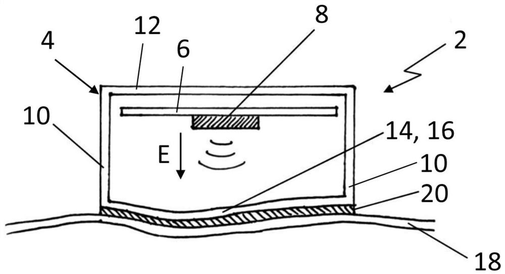
[0035] figure 1 A first exemplary embodiment of a radar measuring device 2 is shown. In this case, the radar measuring device 2 is a radar level measuring device arranged on the wall 18 of the container (not shown) for measuring the level of the content inside the container.

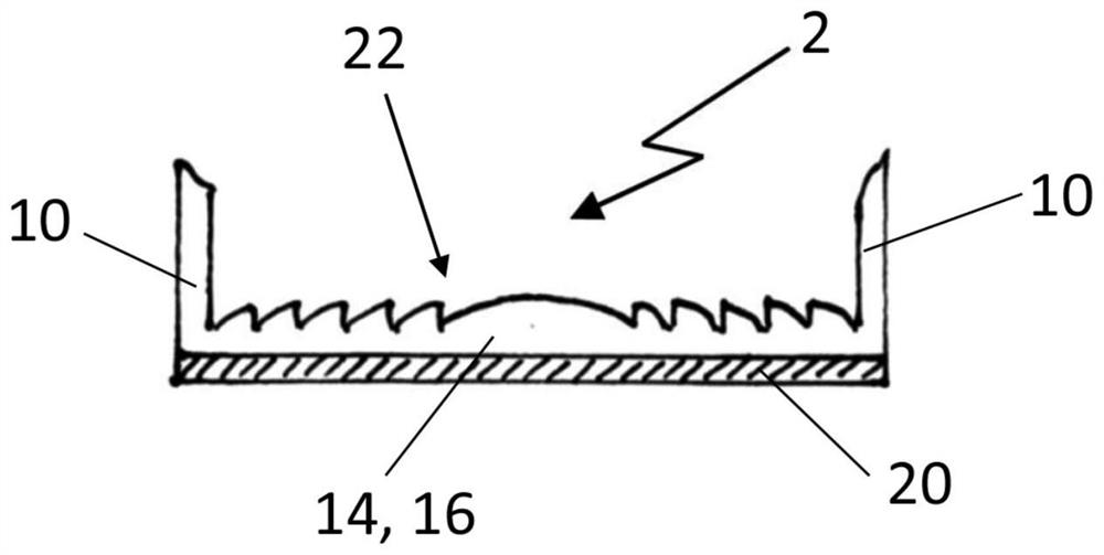
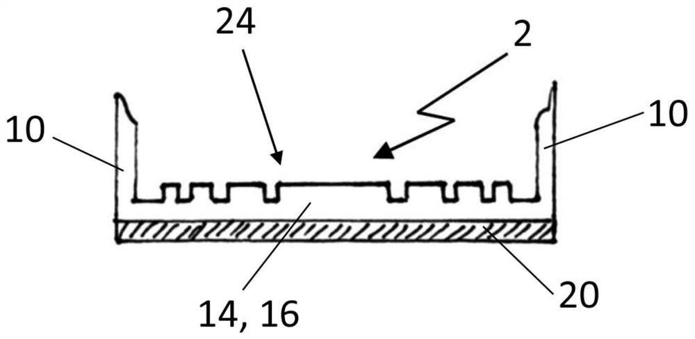
[0036] The radar measuring device 2 is surrounded by a housing 4, the inside of which contains a printed circuit board 6 with a transmitting and receiving unit 8 for generating, transmitting and receiving electromagnetic waves. In this embodiment, the transmitting and receiving unit 8 is a radar chip with an integrated primary exciter inside the housing 4 . exist figure 1 The main emission direction E extending downward from the transceiver unit 8 is shown in . The housing 4 has two flex-resistant side walls 10 and a flex-resistant rear wall 12 . The housing 4 also has a part 14 (in the illustrated case a housing wall 16 ) which is elastically deformable and which is oriented towards the main emissio...


PUM


Abstract

The invention discloses a radar measurement device (2) with at least one transmitter (8) to emit electromagnetic waves, the at least one transmitter (8) being arranged inside a housing (4). The radar measurement device (2) is intended to be securely and lastingly attachable to a flexible wall (18). For this purpose, at least a portion (14) of the housing (4) has an elastically deformable design. Furthermore, the arrangement of a radar measurement device (2) to a fillable container is described.

Description

technical field [0001] The invention relates to a radar measuring device according to the general term used in claim 1 . In particular, the invention relates to a radar level measuring device that can be used to measure the level of a filling in a container. The invention also relates to the arrangement of such a radar measuring device on a container with walls of flexible design. Background technique [0002] Various embodiments of fill level measuring devices for determining and / or monitoring a fill level in a container are known. Radar level measuring devices, such as those operating according to the transit time principle, emit pulses of electromagnetic radiation of a certain wavelength and then detect the temporal variation of the reflected electromagnetic radiation as an echo curve. Furthermore, these devices in particular detect reflections on the surface of the liquid to be tested and / or on the surface of the container content. The sum of the reflections then prod...

Claims


Application Information

Patent Timeline
Patent Type & Authority Applications(China)
IPC IPC(8): G01F23/284G01S7/02
CPCG01F23/284G01S7/03G01S13/88G01S7/027H01Q1/225H01Q1/422H01Q1/427H01Q15/08H01Q19/062
Inventor 罗兰·韦勒莱温·迪特尔勒
Owner VEGA GRIESHABER GMBH & CO
Learn More