Suction plate

A suction cup and pad technology, applied in suction cups, connecting components, supporting machines, etc., can solve the problems of complex overall structure, cost, time and effort, and user inconvenience.

Inactive Publication Date: 2016-09-14
株式会社喜匹喜
View PDF4 Cites 3 Cited by
  • Summary
  • Abstract
  • Description
  • Claims
  • Application Information

AI Technical Summary

Problems solved by technology

[0005] As such, the conventional support is configured to employ an actuating lever to attach the suction cup to glass or the like, and thus has a problem of complicating the overall structure and requiring cost, time, and effort in manufacture
[0006] Furthermore, it is inconvenient for the user to have to pull the actuation lever to attach the support to the glass etc.

Method used


Image

  • Suction plate
  • Suction plate
  • Suction plate

Examples


Embodiment Construction

[0019] Regarding the above-mentioned problems, solutions, and effects, an exemplary embodiment of a suction cup according to an embodiment of the present invention will be described in detail below with reference to the accompanying drawings.

[0020] For clarity and ease of description, the size and shape of elements may be exaggerated in the drawings. In addition, terms specifically defined in view of the structure and function of the element can be changed according to the intentions and habits of users and operators. The definition of these terms must be based on the description throughout this specification.

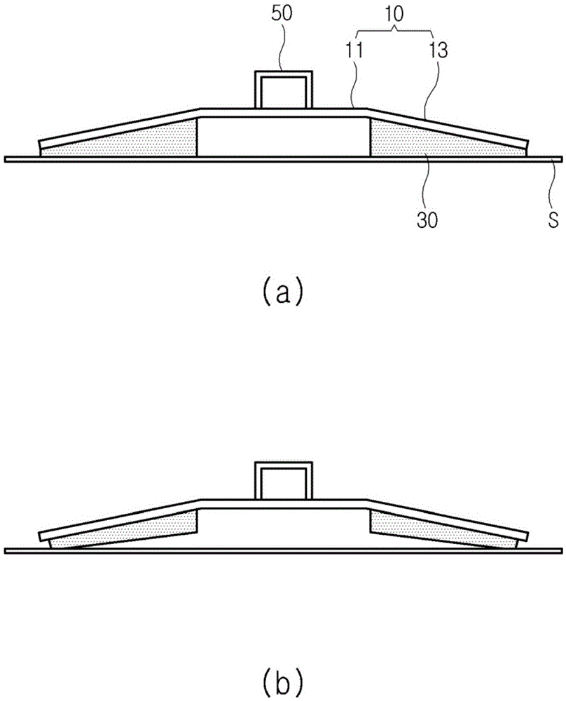
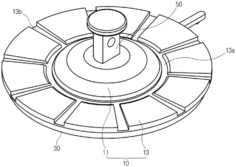
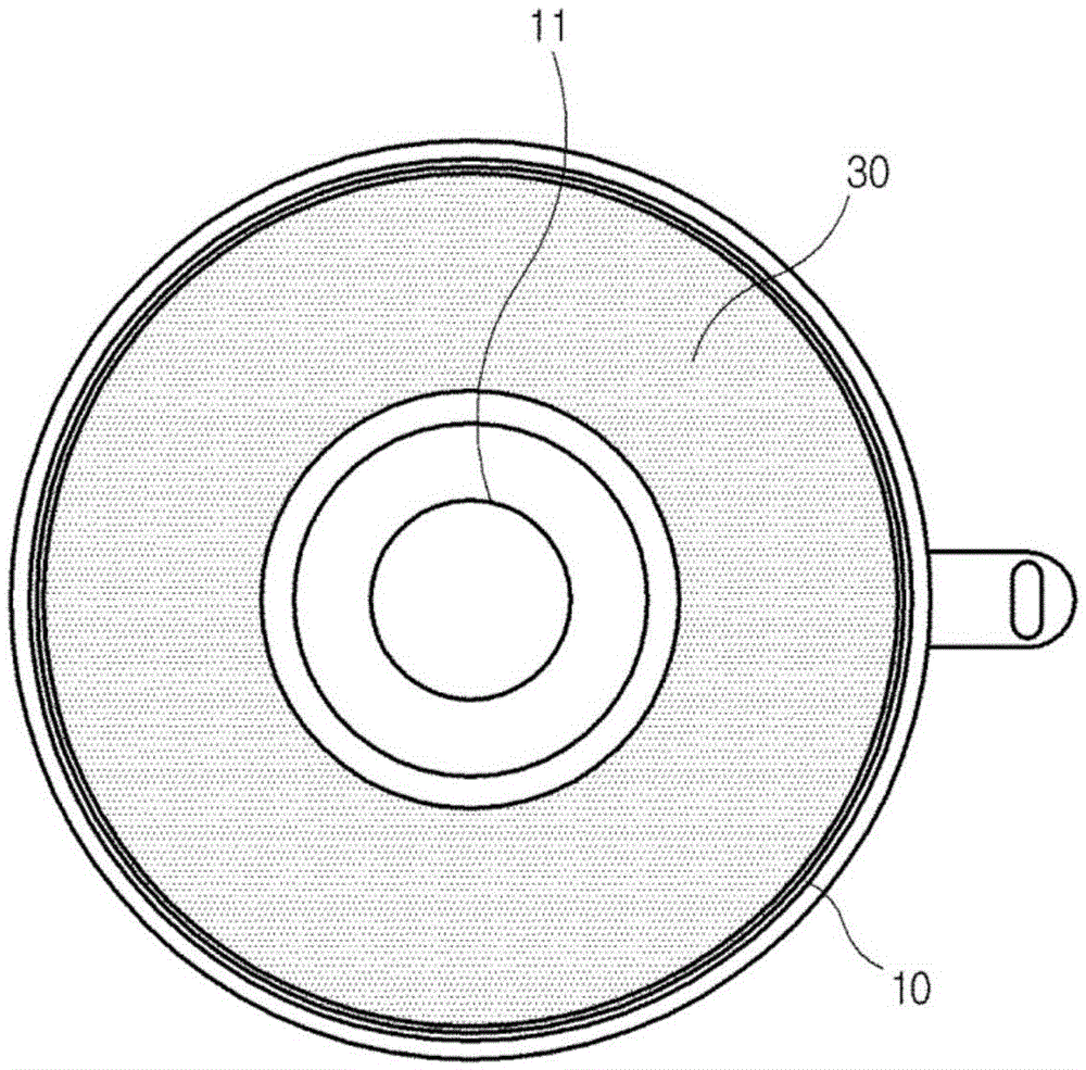
[0021] Such as Figure 1 to Figure 4 As shown in, the suction cup according to the embodiment of the present invention includes a gasket 10, a suction tape 30 attached to the outer bottom surface of the gasket 10, and a connector 50 vertically formed on the top end of the gasket 10.

[0022] The liner 10 is approximately shaped like a disc, and the middle part (central pa...


PUM


Abstract

Disclosed is a suction plate and, more particularly, a suction plate in which a suction belt is pressed down via external force along a liner to which an outer bottom surface is attached to while contacting a target surface and then is restored upwardly when released from the external force, so that a vacuum can be formed between the central part of the liner and the target surface. Because when a user presses the liner against the target surface and releases the liner, the outside of the liner is firmly attached to the target surface via the suction belt and a central part which does not have the suction belt tends to move upward via restoring force, thereby firmly attaching the pad to the target surface.

Description

Technical field [0001] The present invention relates to a suction cup for a support, and more particularly, to a suction cup for a support in which a pad is attached with a suction tape, and more particularly, to the following suction cup: in the suction cup, the pad- The suction tape is attached to the liner along the outer bottom surface-is pressed down by an external force while contacting the target surface and then recovers upward when released from the external force, so that it can be between the center portion of the liner and the target surface A vacuum is formed because when the user presses the liner against the target surface and releases the liner, the outside of the liner is firmly attached to the target surface by the suction tape and the central portion without the suction tape tends to move upward by the restoring force Move, thereby firmly attaching the pad to the target surface. Background technique [0002] At present, various supports for installing convenie...

Claims


Application Information

Patent Timeline
Patent Type & Authority Applications(China)
IPC IPC(8): F16B47/00
CPCF16B47/00F16M13/00F16M13/022
Inventor 宋淳荣
Owner 株式会社喜匹喜
Why Eureka
Try Eureka