Crop drying device with rapid drying function

A technology of rapid drying and drying equipment, which is applied in the direction of drying, drying machines, drying solid materials, etc., and can solve the problems of reducing the drying efficiency of crops, rotten crops, and poor drying effect

Inactive Publication Date: 2021-04-23
吴丹丹
View PDF0 Cites 3 Cited by
  • Summary
  • Abstract
  • Description
  • Claims
  • Application Information

AI Technical Summary

Problems solved by technology

[0002] Some crops, such as wheat, corn, rice, beans, etc., need to be dried in time to remove the water after they are harvested. At present, most crops are still dried by self-heating. This traditional drying method is affected by the weather, and sometimes continuous bad weather It will cause the crops to rot because they are not dried in time, so the crop drying device is very necessary. For the crop drying device, there are the following problems:
[0003] Most of the current crop drying devices just blow the hot air to the crops continuously, but this will only dry the crops above, and the crops located below or in the middle cannot be dried, making the drying effect poor, and the crops are dried during drying. When dry, the crops will emit water vapor. If the water vapor is not treated, the water vapor may condense into water droplets and fall back into the crops, reducing the drying efficiency of the crops. How to solve these problems is what we need to consider

Method used


Image

  • Crop drying device with rapid drying function
  • Crop drying device with rapid drying function
  • Crop drying device with rapid drying function

Examples


Embodiment 1

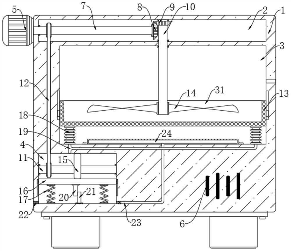
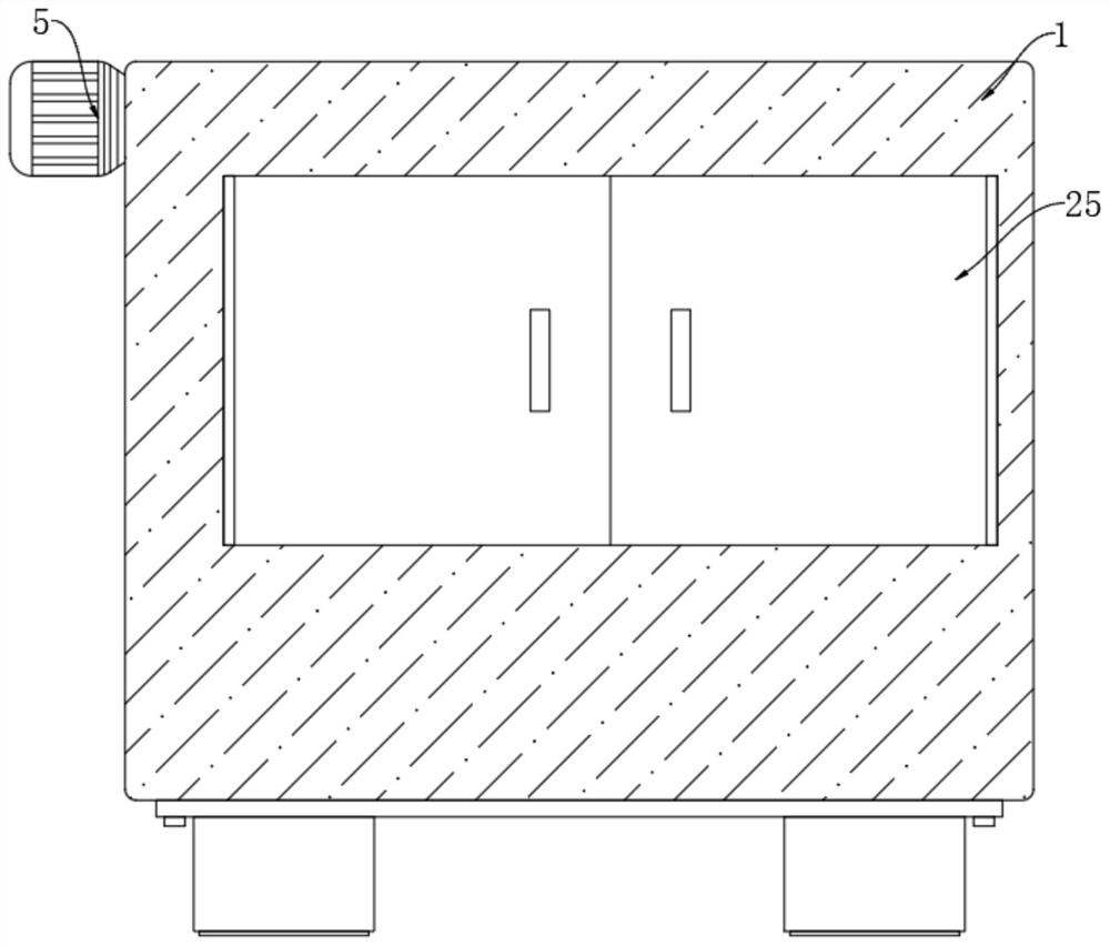
[0022] refer to Figure 1-2 , a crop drying device with fast drying function, comprising a box body 1, the box body 1 is sequentially provided with a rotating chamber 2, a working chamber 3 and a moving chamber 4 from top to bottom, and the front inner wall of the working chamber 3 is provided with An opening communicating with the outside world, on which a sliding door 25 is installed;

[0023] Trigger mechanism, the trigger mechanism includes a first rotating rod 7 horizontally arranged in the rotating chamber 2, a motor 5 is installed on the left side wall of the box body 1, the output shaft end of the motor 5 extends into the rotating chamber 2, and is connected with the first rotating rod. The left end of rod 7 is fixedly connected, and the right end of first rotating rod 7 is fixedly connected with first bevel gear 8, and vertically is provided with second rotating rod 10 in rotating chamber 2, and the upper end of second rotating rod 10 is connected with the interior of...

Embodiment 2

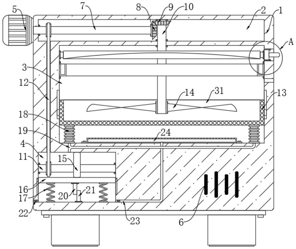
[0032] refer to Figure 3-4 The difference between this embodiment and Embodiment 1 is that the right inner wall of the working chamber 3 is provided with a port 26 communicating with the outside world, and a cooling plate 27 is installed in the port 26, the cooling plate 27, the motor 5 and the power supply 6 Electrically connected in turn, the second rotating rod 10 is fixedly connected with a circular plate 28, the lower end of the circular plate 28 is provided with a groove 29, the inner wall of the working chamber 3 is fixedly connected with a ring-shaped heat-conducting block 30, the right end of the ring-shaped heat-conducting block 30 Contact with the cooling sheet 27, so that the heat in the annular heat conducting block 30 can be introduced into the cooling sheet 27, the inner side wall of the annular heat conducting block 30 is in contact with the circular plate 28, the circular plate 28 is a heat conducting material, and the heat in the circular plate 28 The heat i...


PUM


Abstract

The invention discloses a crop drying device with a rapid drying function. The crop drying device comprises a box body and a triggering mechanism. The box body is sequentially provided with a rotating cavity, a working cavity and a moving cavity from top to bottom, an opening communicating with the outside is formed in the inner wall of the front side of the working cavity, and a sliding door is installed on the opening. The triggering mechanism comprises a first rotating rod horizontally arranged in the rotating cavity, a motor is installed on the left side wall of the box body, and the tail end of an output shaft of the motor extends into the rotating cavity. The device stirs and shakes crops, so that the crops are always in a flowing state, when hot air is sprayed to the crops, the crops can be dried in all directions, the drying effect is better, water vapor is condensed into water drops, the water drops are thrown into a collecting tank through centrifugal force to be collected, and the water drops are prevented from falling into the crops again.

Description

technical field [0001] The invention relates to the field of crop drying, in particular to a crop drying device with a fast drying function. Background technique [0002] Some crops, such as wheat, corn, rice, beans, etc., need to be dried in time to remove the water after they are harvested. At present, most crops are still dried by self-heating. This traditional drying method is affected by the weather, and sometimes continuous bad weather It will cause the crops to rot because they are not dried in time, so the crop drying device is very necessary. For the crop drying device, there are the following problems: [0003] Most of the current crop drying devices just blow the hot air to the crops continuously, but this will only dry the crops above, and the crops located below or in the middle cannot be dried, making the drying effect poor, and the crops are dried during drying. When drying, the crops will emit water vapor. If the water vapor is not treated, the water vapor m...

Claims


Application Information

Patent Timeline
Patent Type & Authority Applications(China)
IPC IPC(8): F26B11/20F26B21/00F26B25/00F26B25/04F26B25/18F28B5/00F28B9/08
CPCF26B11/20F26B21/004F26B25/00F26B25/04F26B25/18F28B5/00F28B9/08
Inventor 吴丹丹杨凤学
Owner 吴丹丹
Why Eureka
Try Eureka