
High-pressure tank with balance pressure stabilizing structure

A high-pressure tank and voltage stabilizing technology, which is applied in the direction of oil tank trucks, pressure vessels, and vehicles used for freight transportation, etc., can solve the problems of high protection effect of the tank body, damage of the tank body, troubles for users, etc., and achieve convenient and convenient daily operations. High protective effect

Inactive Publication Date: 2021-04-23
江苏凡煜机械科技有限公司
View PDF6 Cites 0 Cited by
  • Summary
  • Abstract
  • Description
  • Claims
  • Application Information

AI Technical Summary

Problems solved by technology

[0004] The purpose of the present invention is to provide a high-pressure tank with a balanced pressure-stabilizing structure to solve the problem that the existing high-pressure tank proposed in the background art is not suitable for transportation due to its own shock-absorbing and anti-buffering structures during daily transportation or use. The tank body in it forms a high protective effect, and when the transport vehicle collides on the way, it is easy to cause inevitable damage to the tank body, which brings trouble and danger to the user

Method used


Image

  • High-pressure tank with balance pressure stabilizing structure
  • High-pressure tank with balance pressure stabilizing structure
  • High-pressure tank with balance pressure stabilizing structure

Examples


Embodiment Construction

[0028] The following will clearly and completely describe the technical solutions in the embodiments of the present invention with reference to the accompanying drawings in the embodiments of the present invention. Obviously, the described embodiments are only some, not all, embodiments of the present invention. Based on the embodiments of the present invention, all other embodiments obtained by persons of ordinary skill in the art without making creative efforts belong to the protection scope of the present invention.

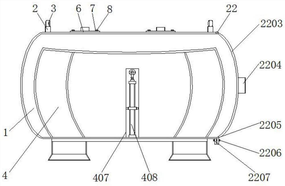
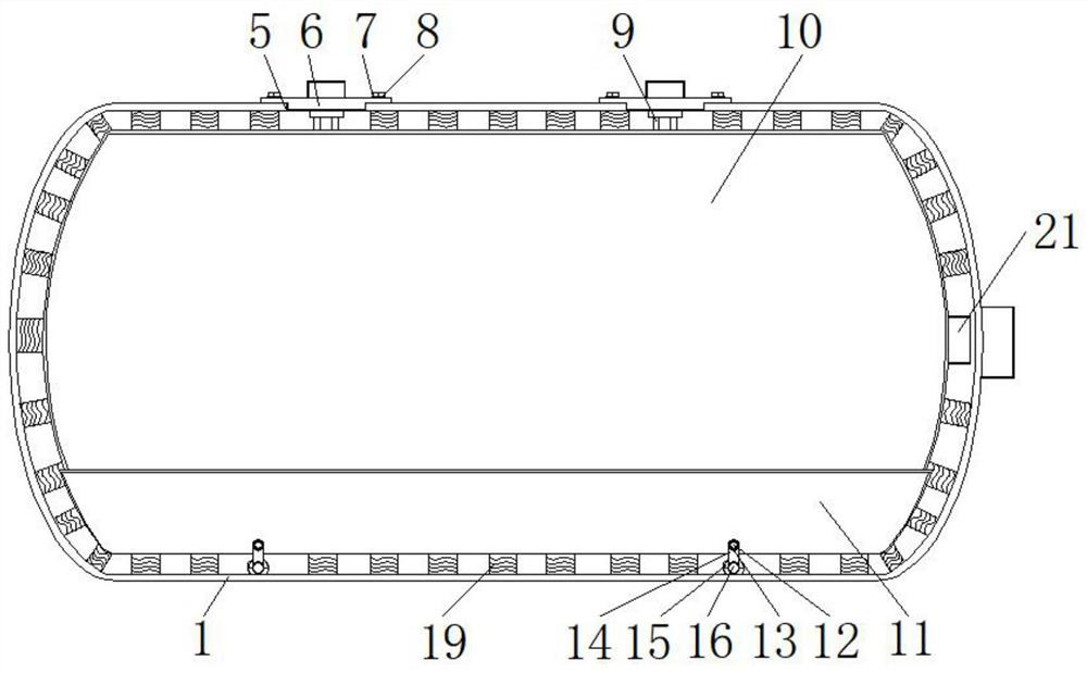
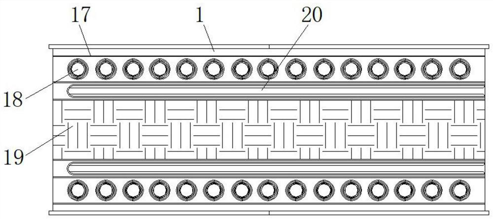
[0029] see Figure 1-7, the present invention provides a technical solution: a high-pressure tank with a balanced and stable pressure structure, including a tank body 1, a fixed block 2, a suspension ring 3, a sliding support mechanism 4, a support seat 401, a directional slide rail 402, a slider 403, Limiting arc plate 404, damping cotton 405, adjusting screw rod 406, third rotating shaft 407, hydraulic rod 408, movable rotating shaft 409, embedding port 5, e...


PUM


Abstract

The invention relates to a high-pressure tank with a balance pressure stabilizing structure. The high-pressure tank comprises a tank body, a sliding supporting mechanism and a rotary fixing mechanism, wherein fixed blocks are fixed to the two sides of the top end of the tank body, lifting rings are welded to the top ends of the fixed blocks, the sliding supporting mechanism is arranged on the outer side of the tank body, embedding openings are formed in the position, close to the middle, of the top end of the tank body, an embedded frame is attached to the inner wall of each embedding opening, threaded holes are formed in the middle portions of the two sides of each embedded frame, bolts are attached to the inner walls of the threaded holes, an air inlet is formed in the lower portion of each embedded frame, the bottom ends of the air inlets are connected with an inner tank body, and a limiting frame is attached to the outer wall of the periphery of the lower portion of the inner tank body. According to the high-pressure tank, the embedded frames are arranged, the embedded frames, the bolts and the tank body form a detachable structure through the threaded holes, and when the air inlets and the inner tank body are jointly placed in the tank body, high protection can be brought to the air inlets and the inner tank body in the daily transport or use process, and meanwhile a user can conveniently detach the tank body and the inner tank body.

Description

technical field [0001] The invention relates to the technical field of high-pressure tanks, in particular to a high-pressure tank with a balanced and stable pressure structure. Background technique [0002] High-pressure tanks that store gases under high pressure, such as hydrogen, require high pressure resistance. For example, accidental collisions during manufacturing or transportation cause changes in the volume of the high-pressure tank, which may cause damage to the tank during transportation or use of the high-pressure tank. gas leakage or even explosion. [0003] In the daily transportation or use of existing high-pressure tanks, their own shock-absorbing and anti-buffer structures cannot form a high protective effect on the tank body during transportation, and when the transport vehicle collides on the way, it is easy to cause damage to the tank body. Avoid damage, thereby causing trouble and danger to users. Contents of the invention [0004] The purpose of the ...

Claims


Application Information

Patent Timeline
Patent Type & Authority Applications(China)
IPC IPC(8): F17C1/04F17C13/00F17C13/08F17C13/12B60P3/22
CPCF17C1/04F17C13/00F17C13/083F17C13/126B60P3/2205
Inventor 李加楠孟庆良关倩陈红刘友华李海南
Owner 江苏凡煜机械科技有限公司
Learn More