
Efficient axial flow fan impeller

A high-efficiency axial flow fan technology, applied in mechanical equipment, machines/engines, liquid fuel engines, etc., can solve the problems of large impeller resistance, automatic adjustment, and affecting the efficiency of impeller speed-up, so as to improve efficiency and strengthen clamping and fixing Effect

Active Publication Date: 2021-04-23
高峰
View PDF6 Cites 0 Cited by
  • Summary
  • Abstract
  • Description
  • Claims
  • Application Information

AI Technical Summary

Problems solved by technology

[0003] In the process of realizing the present invention, the inventor found that at least the following problems in the prior art have not been solved: the blade inclination angle of the impeller in the prior art is difficult to be automatically adjusted according to the

Method used


Image

  • Efficient axial flow fan impeller
  • Efficient axial flow fan impeller
  • Efficient axial flow fan impeller

Examples


Embodiment Construction

[0028] The following will clearly and completely describe the technical solutions in the embodiments of the present invention with reference to the accompanying drawings in the embodiments of the present invention. Obviously, the described embodiments are only some, not all, embodiments of the present invention. Based on the embodiments of the present invention, all other embodiments obtained by persons of ordinary skill in the art without making creative efforts belong to the protection scope of the present invention.

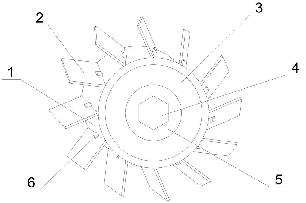
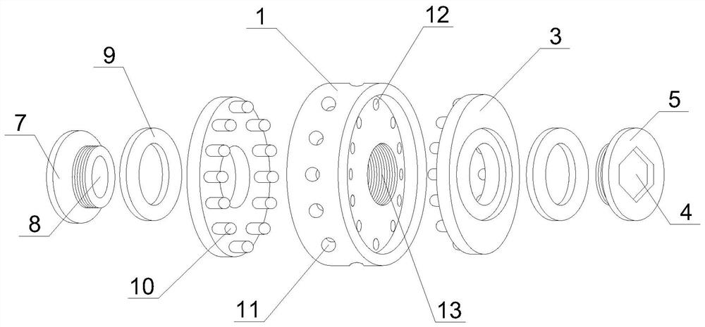
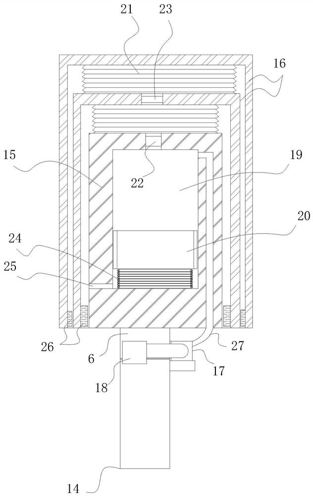
[0029] see Figure 1 to Figure 5 , the present invention provides a technical solution:

[0030] A high-efficiency axial flow fan impeller, such as Figure 1 to Figure 4 As shown, it includes a wheel disc 1, a circle of blades 2 is installed on the periphery of the wheel disc 1, a connecting column 6 is installed near the middle of the lower end of the blade 2, and fastening pins are installed at the middle of the front and rear ends of the wheel disc 1. The...


PUM


Abstract

The invention discloses an efficient axial flow fan impeller. The efficient axial flow fan impeller comprises a wheel disc, a circle of blades are arranged on the periphery of the wheel disc, a connecting column is arranged in the middle of the lower end of each blade, fastening cushion discs are arranged in the middles of the front end and the rear end of the wheel disc correspondingly, a fastening screw tail is arranged in the middle of the fastening cushion disc located at the rear end, a fastening screw head is arranged in the middle of the fastening cushion disc located at the front end, backing rings are arranged between the contact faces of the fastening screw tail and the fastening cushion disc and between the contact faces of the fastening screw head and the fastening cushion disc, a plurality of fastening columns are arranged on one side of the fastening cushion disc, fastening holes corresponding to the fastening columns are formed in the front end and the rear end of the wheel disc in a penetrating mode, a circle of fastening grooves are formed in the middle of the front end and the rear end of the wheel disc, and connecting pieces are arranged between the connecting columns and the fastening grooves. The blades can automatically adjust the inclination angle during rotation, so that the starting resistance of the impeller is effectively reduced, and the safety of driving the impeller to rotate is guaranteed.

Description

technical field [0001] The invention relates to the field of fans, in particular to a high-efficiency axial flow fan impeller. Background technique [0002] The fan is a machine that relies on the input mechanical energy to increase the gas pressure and discharge the gas. It is a driven fluid machine. There are many types of fans. Different types of fans are equipped with different fan impellers. The axial flow fan is a kind of axial flow machine. The airflow is in the same direction as the axis of the fan blades, and the impeller is a high-efficiency axial flow fan impeller. [0003] In the process of realizing the present invention, the inventor found that at least the following problems in the prior art have not been solved: the blade inclination angle of the impeller in the prior art is difficult to be automatically adjusted according to the actual rotational speed of the impeller, resulting in a large resistance when the impeller starts, affecting This reduces the effi...

Claims


Application Information

Patent Timeline
IPC IPC(8): F04D29/32F04D29/36F04D29/64F04D29/70
CPCF04D29/325F04D29/362F04D29/644F04D29/701
Inventor 柳丽阎勇
Owner 高峰
Learn More