
Axial flow fan impeller

An axial flow fan and impeller technology, applied in mechanical equipment, machines/engines, liquid fuel engines, etc., can solve problems such as improving efficiency, inability to adjust the number of blades, and easily scratching staff, and achieve the effect of ensuring normal work.

Pending Publication Date: 2021-03-16
柳丽
View PDF9 Cites 0 Cited by
  • Summary
  • Abstract
  • Description
  • Claims
  • Application Information

AI Technical Summary

Problems solved by technology

[0003] In the process of realizing the present invention, the inventor found that at least the following problems in the prior art have not been resolved: 1. The number of blades of the existing high-efficiency axial flow fan impeller is fixed, and the number of blades cannot be adjusted according to demand to improve efficiency; 2. The impeller components of the existing high-efficiency axial flow fan are integrated and cannot be disassembled. If one of the components is damaged, the entire fan impeller must be replaced; 3. When the axial flow fan needs to be disassembled for repair or maintenance, because the impeller The edge is sharp, and the blades are easy to scratch the staff, especially for large axial flow fans, the larger blades used are more likely to scratch the staff

Method used


Image

  • Axial flow fan impeller
  • Axial flow fan impeller
  • Axial flow fan impeller

Examples


specific Embodiment approach

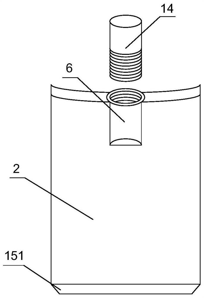
[0028] As a specific embodiment of the present invention, the anti-scratch unit 15 includes a hollow nylon layer 151, the hollow nylon layer 151 is fixed to the edge of the blade 2, and the end of the hollow nylon layer 151 away from the blade 2 is sharp; The nylon layer 151 is filled with a magneto-rheological fluid 152; the interior of the blade 2 is filled with an electromagnet 153, and the electromagnet 153 is energized to change the fluidity of the magnetorheological fluid 152;

[0029] When the axial flow fan is working, the electromagnet 153 can be energized to form a magnetic field in the blade 2, so that the magnetorheological fluid 152 in the hollow nylon layer 151 presents the characteristics of high viscosity and low fluidity, so that the hollow nylon layer 151 The filling is tight, and the end of the hollow nylon layer 151 away from the blade 2 is sharp, so as to prevent the hollow nylon layer 151 from affecting the rotation speed of the blade 2, resulting in a red...


PUM


Abstract

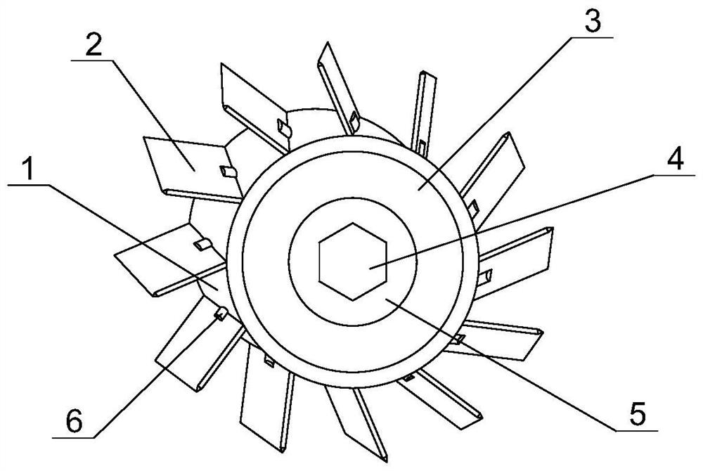
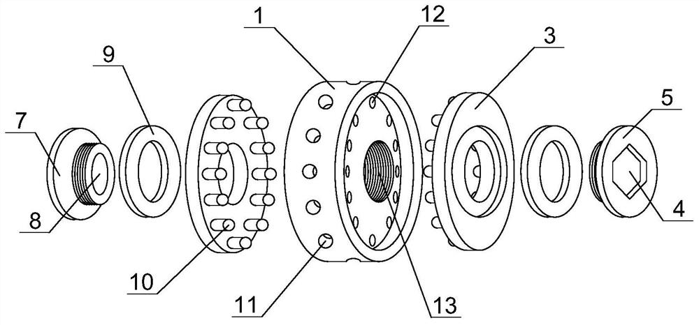
The invention discloses an axial flow fan impeller which comprises a wheel disc, a circle of blades are mounted on the periphery of the wheel disc, fixing screw holes are formed in the middles of thelower ends of the blades, fastening cushion discs are mounted at the front end and the rear end, close to the middle, of the wheel disc, a fastening screw tail is mounted at the middle of the fastening cushion disc located at the rear end, a fastening screw head is mounted at the middle of the fastening cushion disc located at the front end, backing rings are mounted between a contact surface of the fastening screw tail and the fastening cushion disc and between a contact surface of the fastening screw head and the fastening cushion disc, a plurality of fastening columns are mounted at one side of the fastening cushion disc, fastening holes corresponding to the fastening columns are formed in the front end and the rear end of the wheel disc in a penetrating mode, a circle of fastening grooves are formed in the front end and the rear end, close to the middle, of the wheel disc, and a connecting piece is mounted between the fixing screw hole and the fastening groove. According to the axial flow fan impeller, the number and the distance of the blades can be adjusted according to the requirement, the efficiency is improved, and after components of the fan impeller are damaged, a singlecomponent can be replaced without replacing the whole fan impeller.

Description

technical field [0001] The invention relates to the field of fans, in particular to an impeller of an axial flow fan. Background technique [0002] The fan is a machine that relies on the input mechanical energy to increase the gas pressure and discharge the gas. It is a driven fluid machine. There are many types of fans. Different types of fans are equipped with different fan impellers. The axial flow fan is a kind of axial flow machine. The airflow is in the same direction as the axis of the fan blades, and the impeller is a high-efficiency axial flow fan impeller. [0003] In the process of realizing the present invention, the inventor found that at least the following problems in the prior art have not been resolved: 1. The number of blades of the existing high-efficiency axial flow fan impeller is fixed, and the number of blades cannot be adjusted according to demand to improve efficiency; 2. All the components of the existing high-efficiency axial flow fan impeller ar...

Claims


Application Information

Patent Timeline
IPC IPC(8): F04D29/32F04D29/34F04D29/64
CPCF04D29/325F04D29/34F04D29/646F04D29/263
Inventor 柳丽阎勇
Owner 柳丽
Learn More