
Tower crane connecting structure

A technology for connecting structures and tower cranes, which is applied in elevators, elevators in buildings, transportation and packaging, etc., and can solve the problems of inability to guarantee the safety of personnel moving up and down, poor expandability, and unstable structure of the upper and lower transportation devices.

Active Publication Date: 2021-04-23
LUOHE VOCATIONAL TECH COLLEGE
View PDF11 Cites 0 Cited by
  • Summary
  • Abstract
  • Description
  • Claims
  • Application Information

AI Technical Summary

Problems solved by technology

[0003] The operating room of the existing tower crane is mostly fixedly connected to the tower crane, and the connection structure is simple. It is directly fixed on the tower crane, causing the operator to manually climb up and down when moving up and down, which is very inconvenient and cannot effectively move the top and bottom. The transportation connection affects the efficiency and poor safety. At the same time, the structure of the existing upper and lower transportation devices is unstable, which leads to the inability to guarantee the safety of personnel moving up and down, and the expansion is poor.

Method used

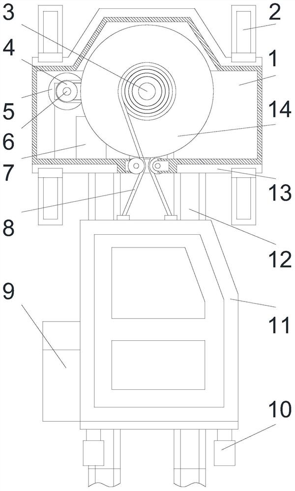
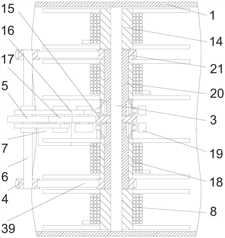
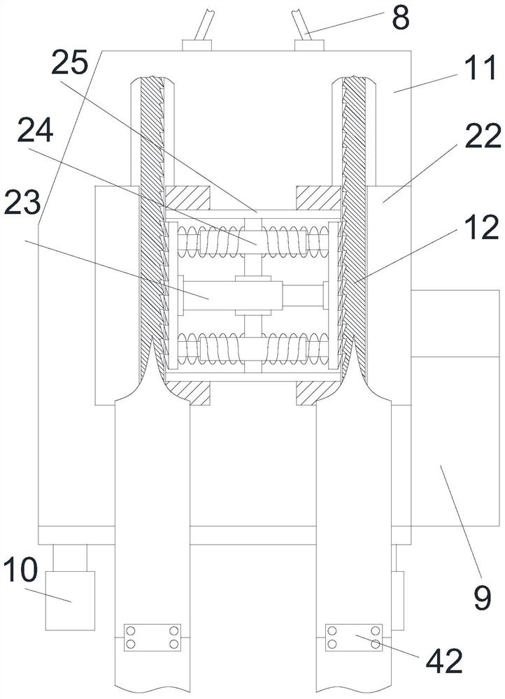

Image

  • Tower crane connecting structure
  • Tower crane connecting structure
  • Tower crane connecting structure

Examples


Embodiment Construction

[0024] The following will clearly and completely describe the technical solutions in the embodiments of the present invention with reference to the accompanying drawings in the embodiments of the present invention. Obviously, the described embodiments are only some, not all, embodiments of the present invention. Based on the embodiments of the present invention, all other embodiments obtained by persons of ordinary skill in the art without making creative efforts belong to the protection scope of the present invention.

[0025] In describing the present invention, it is to be understood that the terms "center", "upper", "lower", "front", "rear", "left", "right", "vertical", "horizontal", The orientations or positional relationships indicated by "top", "bottom", "inner", "outer", etc. are based on the orientations or positional relationships shown in the drawings, and are only for the convenience of describing the present invention and simplifying the description, rather than in...


PUM


Abstract

The invention discloses a tower crane connecting structure which mainly comprises an outer frame, a side shaft, a motor, a steel cable, a control box, a lift car, guide rails, an electromagnetic meshing frame, sliding seats and a locking box. Reinforcing frames are fixedly installed at the upper end and the lower end of the outer frame, and triangular supports which are symmetrically arranged are fixedly installed at the edges of the reinforcing frames. A middle shaft is rotatably installed in the middle of the inner side of the outer frame, outer winding frames which are symmetrical front and back are fixedly installed on the outer side of the middle shaft, rotating sleeves which are symmetrical front and back are rotatably installed in the middle of the outer side of the middle shaft, and inner winding frames are fixedly installed on the outer sides of the rotating sleeves. The tower crane connecting structure is reasonable in structural design, and through the flexible and reasonable connecting structure, the lift car can move up and down to convey people. The connecting structure is high in expansibility, adapts to the using environment of a tower crane, and has higher safety. Besides, double lock shafts and a reasonable anti-falling structure are arranged, through a gentle slow falling mode, people in the lift car are prevented from being impacted instantaneously during stop, and use is safer. Meanwhile, active steel cable detection is achieved, and preventive measures are taken in advance.

Description

technical field [0001] The invention relates to a tower crane device, in particular to a tower crane connection structure. Background technique [0002] Tower crane is the most commonly used lifting equipment on construction sites, also known as "tower crane". , concrete, steel pipe and other construction raw materials. The tower crane is an indispensable equipment on the construction site. The function of the tower crane tip is to bear the upper load from the jib stay rope and the balance arm stay rope, and pass through the structure of the slewing tower, turntable, bearing, etc. The component type is directly transferred to the tower structure through the turntable. The top of the self-elevating tower has a truncated cone column type, a forward or backward inclined truncated cone column type, a herringbone frame type and a diagonal brace type. [0003] The operating room of the existing tower crane is mostly fixedly connected to the tower crane, and the connection struc...

Claims


Application Information

Patent Timeline
Patent Type & Authority Applications(China)
IPC IPC(8): B66B5/18B66B7/02B66B11/02B66B11/04
CPCB66B7/023B66B5/18B66B11/0065B66B11/043B66B11/0266
Inventor 赵君亮周成科刘学曦朱亚辉刘艳娜
Owner LUOHE VOCATIONAL TECH COLLEGE
Learn More