Anti-tearing emergency stop device suitable for belt conveyor head

A belt conveyor and anti-tear technology, applied in conveyor control devices, conveyors, conveyor objects, etc., can solve the problems of conveyor belt breakage, economic loss, and reducing the braking effect of belt conveyors.

Inactive Publication Date: 2021-04-23
安徽宇艳智能机械科技有限公司
View PDF0 Cites 0 Cited by
  • Summary
  • Abstract
  • Description
  • Claims
  • Application Information

AI Technical Summary

Problems solved by technology

[0002] Longitudinal tearing and scratches on the conveyor belt of the belt conveyor are devastating damage, and the loss is the heaviest. Most of the current belt conveyors are equipped with a tear detection device. When the conveyor belt is torn, it will be detected as soon as possible in the shortest time and an alarm will be issued. Signal and shut down to minimize the tearing length and reduce losses. However, the conveyor belt after the shutdown will continue to drive the roller to rotate and move a certain distance under the inertia of itself and the material, which results in that although the belt conveyor can stop in time, but The conveyor belt still has the risk of continuing to expand the tear;
[0003] By installing a braking device on the belt conveyor, the braking distance of the belt conveyor can be effectively reduced. However, the braking mechanism of the belt conveyor is often affected by the tension of the belt. The role of the conveyor belt causes plastic deformation, makes the conveyor belt longer, reduces the friction between the conveyor belt and the pulley and reduces the braking effect of the belt conveyor; by increasing the tension of the conveyor belt, the belt can be effectively improved. However, the existing belt conveyor tensioning mechanism cannot monitor the tension of the conveyor belt. Improving the braking effect of the belt conveyor by increasing the tension can easily cause the conveyor belt to break, which is economically cause more damage

Method used


Image

  • Anti-tearing emergency stop device suitable for belt conveyor head
  • Anti-tearing emergency stop device suitable for belt conveyor head
  • Anti-tearing emergency stop device suitable for belt conveyor head

Examples


Embodiment 1

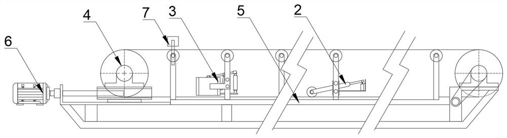
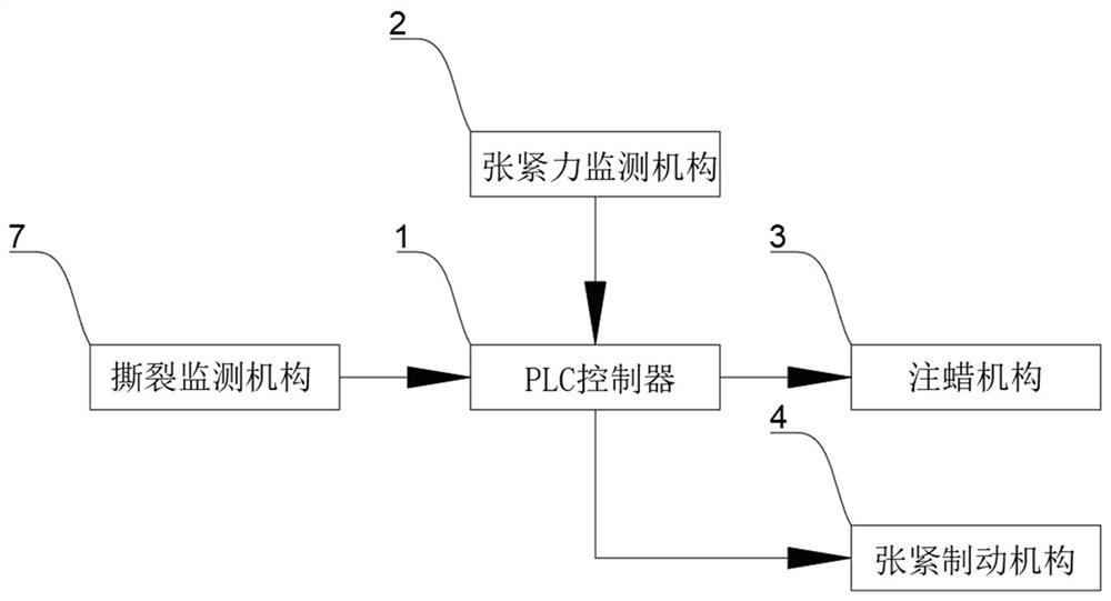
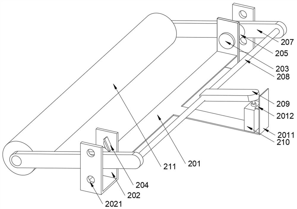
[0027] see Figure 1-Figure 7 , the present invention provides the following technical solutions: an anti-tear emergency stop device suitable for the head of a belt conveyor, including a PLC controller 1, a tension monitoring mechanism 2, a wax injection mechanism 3, a tension brake mechanism 4, a tear The crack monitoring mechanism 7, the tension monitoring mechanism 2 is fixedly installed on the middle side of the belt conveyor 5, the wax injection mechanism 3 is fixedly installed on the tail side of the belt conveyor 5, and the wire in the tension braking mechanism 4 One end of the rod is fixedly connected to the output shaft of the tensioning motor 6, and the tension monitoring mechanism 2 includes a T-shaped frame 201, and the two ends of the T-shaped frame 201 are fixedly connected to the sides of the U-shaped frame 202, and the U-shaped frame The side of 202 is rotatably equipped with a rotating shaft 203, one end of the rotating shaft 203 is fixedly connected to the in...


PUM


Abstract

The invention belongs to the technical field of belt conveyors, and particularly relates to an anti-tearing emergency stop device suitable for a belt conveyor head. The anti-tearing emergency stop device comprises a programmable logic controller (PLC), a tension force monitoring mechanism, a wax injection mechanism, a tension braking mechanism and a tearing monitoring mechanism, wherein the tension force monitoring mechanism and the wax injection mechanism are separately mounted on the middle side and the tail side of a belt conveyor; a lead screw in the tension braking mechanism is fixedly connected to an output shaft of a tension motor; the tension force monitoring mechanism comprises a T-shaped frame, U-shaped frames, rotating shafts, connecting arms, torsion springs, first clamping plates, second clamping plates, a connecting rod, a tail plate, a pressing roller and a travel switch; and the wax injection mechanism comprises a wax injection box, L-shaped frames, a bottom plate, a first U-shaped base, an electric push rod, a pressing rod, a second U-shaped base, a pressing plate, sealing covers, a lower connecting rod, a third U-shaped base and rubber plugs. The PLC can improve the tension degree of the belt conveyor through the tension motor so as to improve the braking effect, and can cooperate with the tension force monitoring mechanism so as to prevent a conveyor belt from being broken due to the overlarge tension degree. The wax injection mechanism can extrude belt wax onto the conveyor belt so as to shorten the braking time.

Description

technical field [0001] The invention belongs to the technical field of belt conveyors, and in particular relates to an anti-tear emergency stop device suitable for belt conveyor heads. Background technique [0002] Longitudinal tearing and scratches on the conveyor belt of the belt conveyor are devastating damage, and the loss is the heaviest. Most of the current belt conveyors are equipped with a tear detection device. When the conveyor belt is torn, it will be detected as soon as possible in the shortest time and an alarm will be issued. Signal and shut down to minimize the tearing length and reduce losses. However, the conveyor belt after the shutdown will continue to drive the roller to rotate and move a certain distance under the inertia of itself and the material, which results in that although the belt conveyor can stop in time, but The conveyor belt still has the risk of continuing to expand the tear; [0003] By installing a braking device on the belt conveyor, the...

Claims


Application Information

Patent Timeline
Patent Type & Authority Applications(China)
IPC IPC(8): B65G43/02B65G23/44
CPCB65G23/44B65G43/02
Inventor 杨俊宇胡学友徐庆辉
Owner 安徽宇艳智能机械科技有限公司
Why Eureka
Try Eureka