
Assembled turbulent flame extinguishing device

A flame extinguishing and assembled technology, applied in fire rescue, teaching models, instruments, etc., can solve problems such as large errors, low accuracy of experimental data, and inability to achieve precise control of gas flow

Active Publication Date: 2021-04-20
ZHENGZHOU UNIV
View PDF16 Cites 1 Cited by
  • Summary
  • Abstract
  • Description
  • Claims
  • Application Information

AI Technical Summary

Problems solved by technology

[0005] Aiming at the deficiencies of the prior art, the present invention provides an assembled turbulent flame extinguishing device, which solves the problem that the existing turbulent flame extinguishing device cannot accurately control the gas flow inside the device, has large errors, and has low accuracy of experimental data. For low-level problems, the application method of traditional fire extinguishing agent and flame confrontation can be changed, the applied component concentration of fire extinguishing agent can be strictly quantitatively measured and the effectiveness of fire extinguishing agent in extinguishing turbulent flames can be evaluated, and the dynamic control of gas entering the flame combustion zone can be realized. The influence of typical characteristics such as turbulent flame structure and color and the effective implementation of dynamic observation experiments can realize dynamic observation of the fire extinguishing performance of fine water mist and halogenated hydrocarbon fire extinguishing agents when they are applied perpendicular to the flame level

Method used


Image

  • Assembled turbulent flame extinguishing device
  • Assembled turbulent flame extinguishing device
  • Assembled turbulent flame extinguishing device

Examples


Embodiment Construction

[0024] The following will clearly and completely describe the technical solutions in the embodiments of the present invention with reference to the accompanying drawings in the embodiments of the present invention. Obviously, the described embodiments are only some, not all, embodiments of the present invention. Based on the embodiments of the present invention, all other embodiments obtained by persons of ordinary skill in the art without making creative efforts belong to the protection scope of the present invention.

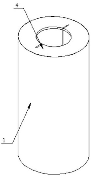
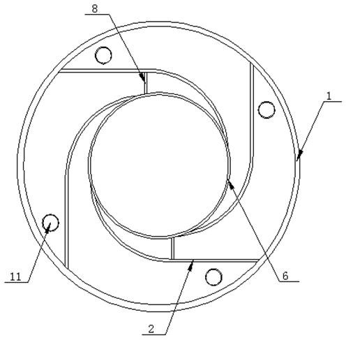
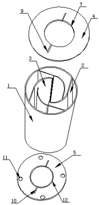
[0025] see Figure 1-4 , the embodiment of the present invention provides a technical solution: an assembled vortex flame device, including a gas box 1, a partition 2 and a curved plate 3, the height of the gas box 1 is 0.54m, and the baffle 8 and the rotating drum 6 The height is 0.56m, the thickness of the top plate 4 and the bottom plate 5 are both 0.005m, there are four partitions 2 and arc-shaped plates 3 located inside the air box 1, and the four partiti...


PUM


Abstract

The invention discloses an assembled turbulent flame extinguishing device, whichrelates to the technical field of fire extinguishing devices, and comprises an air box, a partition plate and an arc-shaped plate, wherein one side of the partition plate is fixedly connected with the inner wall of the air box, and one side of the partition plate is fixedly connected with one side of the arc-shaped plate. According to the assembled turbulent flame extinguishing device, the effect of controlling whether air in the air box circulates or not and controlling the flow speed is achieved through the rotating mode of the rotating drum, air entering is quantitatively controlled through the rotating drum, assistance is provided for providing more accurate fuel mass loss efficiency, and two kinds of air are filled into the air box through the vent holes for an experiment; the flow of air on the opposite side can be controlled at the same time only by rotating the rotating drum, the air flow can be controlled more accurately, errors are smaller, experimental data are more accurate, and the influence of air entering the turbulent flame flow field, the flame structure, the flame color and other typical characteristics can be observed while the rotating drum is rotated; a dynamic observation experiment is realized, and the fire extinguishing performance of the water mist and halogenated hydrocarbon fire extinguishing agent can be dynamically observed.

Description

technical field [0001] The invention relates to the technical field of fire fighting devices, in particular to an assembled turbulent flame extinguishing device. Background technique [0002] Turbulent flames are also called turbulent flames. The waveform and propagation speed of turbulent flames are different from those of laminar flames. The turbulent flame front is constantly shaking, and the flame front is very thick to form a region. The flame propagation velocity is equal to the pulsating velocity, and its size is not only related to the physical and chemical properties and parameters of the combustible gas mixture, but also related to the turbulent state (ie pulsating velocity). This kind of turbulent flame is common in grassland fires and forest fires. It is of great significance to study the causes, control factors and fire extinguishing agents of turbulent flame combustion for forest and grassland fire fighting and fire safety. Currently, the research on turbulent...

Claims


Application Information

Patent Timeline
IPC IPC(8): G01N31/12A62C31/02
CPCG01N31/12A62C31/02G09B25/00Y02A40/28
Inventor 阮晓辉边会婷李静王东明魏子莹靳博阳
Owner ZHENGZHOU UNIV
Learn More