
New energy house wind power generation installation device and installation method thereof

A technology for installing devices and wind turbines, applied in wind power generation, installation/supporting configuration of wind turbines, wind turbines, etc. It can solve the problems of inconvenient steel pipe handling, long cycle time, and no ladders, etc.

Active Publication Date: 2021-04-20
STATE GRID ZHEJIANG ELECTRIC POWER COMPANY TAIZHOU POWER SUPPLY
View PDF6 Cites 1 Cited by
  • Summary
  • Abstract
  • Description
  • Claims
  • Application Information

AI Technical Summary

Problems solved by technology

[0005] The purpose of the present invention is to provide a new energy house wind power generation installation device and its installation method, to solve the problem that most of the wind power generation devices of the new energy house proposed in the above background technology are installed on the support frame, one of which is relatively high due to its high height. Supporting installation through custom-made steel pipes takes a long period of time, and steel pipes are inconvenient to carry. At the same time, steel pipes are mostly installed by welding and bolts. The installation efficiency is low, and it is inconvenient to disassemble later, so the practicability is poor. There is no climbing ladder, which leads to the need to climb the ladder for maintenance, which is a high risk problem

Method used


Image

  • New energy house wind power generation installation device and installation method thereof
  • New energy house wind power generation installation device and installation method thereof
  • New energy house wind power generation installation device and installation method thereof

Examples


Embodiment Construction

[0031] The following will clearly and completely describe the technical solutions in the embodiments of the present invention with reference to the accompanying drawings in the embodiments of the present invention. Obviously, the described embodiments are only some, not all, embodiments of the present invention. Based on the embodiments of the present invention, all other embodiments obtained by persons of ordinary skill in the art without making creative efforts belong to the protection scope of the present invention.

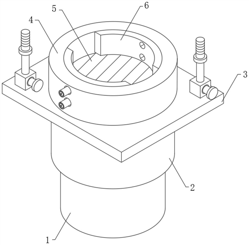
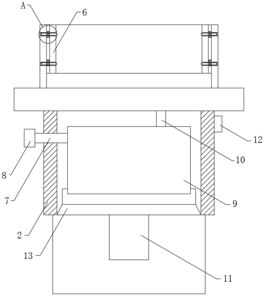
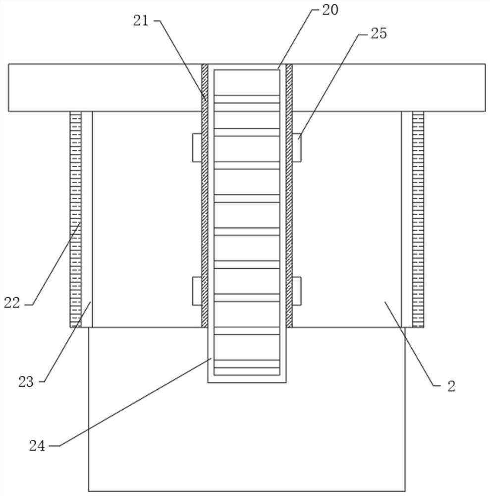
[0032] The present invention provides such Figure 1-6 A new energy house wind power installation device and its installation method are shown, including a cement foundation pile 1, the top of the cement foundation pile 1 is fixed with a protective box 2, and the top of the protective box 2 is fixed with a support base 3 , the top of the support base 3 is fixedly provided with an outer collar 4, and the bottom of the inner cavity of the outer collar 4 is fixed...


PUM


Abstract

The invention discloses a new energy house wind power generation installation device and an installation method thereof. The new energy house wind power generation installation device comprises a cement foundation pile, an outer clamping ring is fixedly arranged at the top end of a supporting base, an electromagnetic suction cup is fixedly arranged at the bottom of an inner cavity of the outer clamping ring, and arc-shaped extrusion plates are connected to the two sides of the inner cavity of the outer clamping ring through compression springs correspondingly, traction structures are fixedly arranged at the positions of the two corners of the top end of the supporting base correspondingly, and a climbing structure is installed on the back face of a protection box body. The outer clamping ring, the electromagnetic suction cup, the arc-shaped extrusion plates, second through holes, limiting shafts, hollow columns, ear rings, the compression springs and first through holes are arranged, and by adjusting the two sets of hollow columns, the distance between the two arc-shaped extrusion plates is increased, and a wind driven generator is conveniently and stably clamped. The wind driven generator continues to be installed downwards, the wind driven generator is made to be in contact connection with the electromagnetic suction cup, the electromagnetic suction cup generates attraction force after being powered on, the wind driven generator can be firmly attracted, and meanwhile, disassembly is convenient and practicability is high.

Description

technical field [0001] The invention relates to the field of new energy technologies, in particular to a wind power installation device for a new energy house and an installation method thereof. Background technique [0002] New energy (NE): also known as unconventional energy. Refers to various forms of energy other than traditional energy. Refers to energy sources that have just begun to be developed and utilized or are being actively researched and yet to be promoted, such as solar energy, geothermal energy, wind energy, ocean energy, biomass energy, and nuclear fusion energy. [0003] Wind power generation refers to the conversion of wind kinetic energy into electrical energy. Wind energy is a clean and pollution-free renewable energy source. It has been used by people for a long time, mainly through windmills to pump water and grind flour. The use of wind to generate electricity is very environmentally friendly and has a huge amount of wind energy, so it is increasing...

Claims


Application Information

Patent Timeline
IPC IPC(8): F03D13/20F03D9/45F03D80/00F03D80/60E06C9/08
CPCY02E70/30
Inventor 韩静
Owner STATE GRID ZHEJIANG ELECTRIC POWER COMPANY TAIZHOU POWER SUPPLY
Learn More