
Floor-type-free pier stud bent cap formwork dismounting and mounting equipment and construction method

A non-floor type, cover beam technology, applied in bridge construction, bridges, bridge parts, etc., can solve problems such as high risk, slow construction, poor safety and accuracy

Pending Publication Date: 2021-04-20
NO 4 ENG COMPANY LTD OF CCCC FIRST HARBOR ENG COMPANY
View PDF0 Cites 0 Cited by
  • Summary
  • Abstract
  • Description
  • Claims
  • Application Information

AI Technical Summary

Problems solved by technology

After the cover beam formwork is installed, pour the cover beam. After pouring, use the tower crane or crane to lift the formwork. During the process of pouring the cover beam, the tower crane or crane needs to be used for a long time, and the tower crane or crane lift When using formwork, the safety and accuracy are poor, the construction is slow and the risk is high

Method used


Image

  • Floor-type-free pier stud bent cap formwork dismounting and mounting equipment and construction method
  • Floor-type-free pier stud bent cap formwork dismounting and mounting equipment and construction method
  • Floor-type-free pier stud bent cap formwork dismounting and mounting equipment and construction method

Examples


Embodiment 1

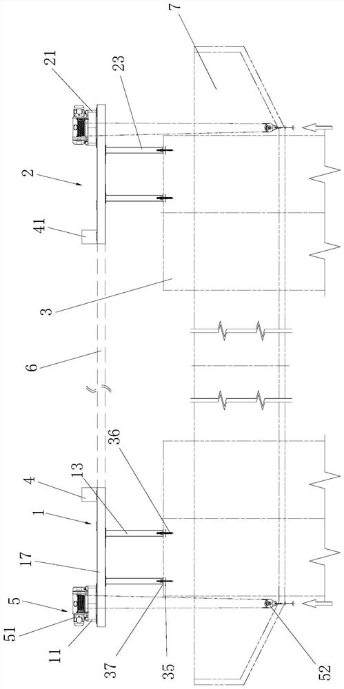
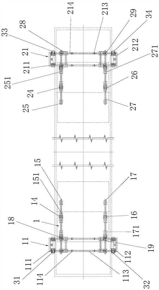
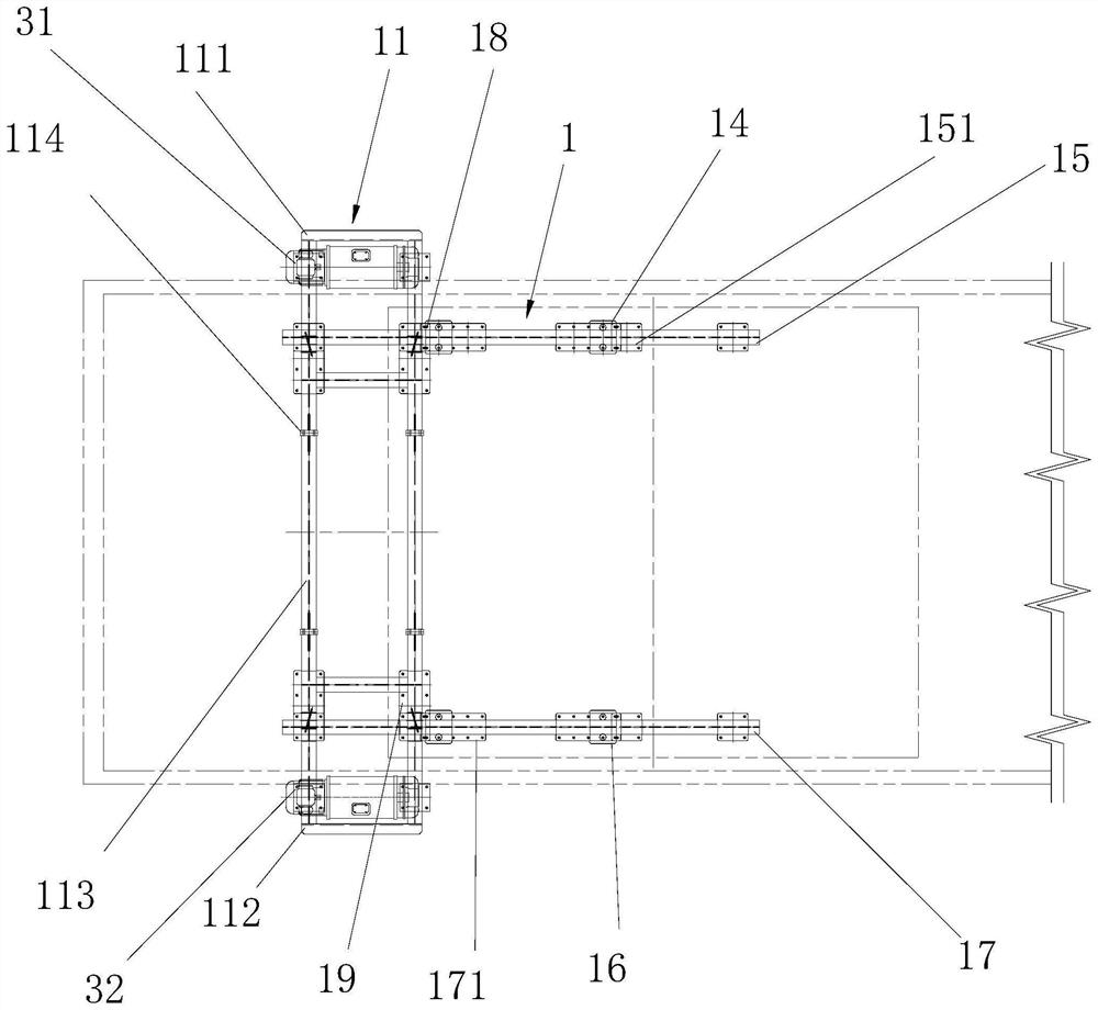
[0055] combine Figure 1 to Figure 9 , a non-floor type pier column cover beam formwork disassembly equipment, including a first support device 1 and a second support device 2, the first support device 1 and the second support device 2 are respectively arranged on two adjacent pier columns 3 the upper end. The first supporting device 1 includes a first motor support frame 11, two first legs 12 and two second legs 13, and the upper ends of the two first legs 11 are adjusted by the first transverse positioning plate 14, the first transverse positioning A first cross brace 15 is connected by bolts, and a second cross brace 17 is connected to the upper ends of the two second legs 12 through the second transverse adjustment positioning plate 16 and the second transverse positioning bolts.

[0056] The left part of the first cross brace 15 is positioned and connected with the first motor support frame 11 through the first longitudinal adjustment positioning plate 18, the first long...

Embodiment 2

[0080] combine Figure 1 to Figure 9 , a construction method of pier column cover beams, using the above-mentioned non-floor type pier column cover beam formwork disassembly equipment, specifically includes the following steps:

[0081]Step A, the first electric hoist is connected to the first front U-shaped frame through the first motor positioning base, the second electric hoist is connected to the first rear U-shaped frame through the second motor positioning base, and the first electric hoist is connected with bolts. The front U-shaped frame and the first rear U-shaped frame; the third electric hoist is connected to the second front U-shaped frame through the third motor positioning base, and the fourth electric hoist is connected to the second rear U-shaped frame through the fourth motor positioning base On the shaped frame, use bolts to connect the second front U-shaped frame and the second rear U-shaped frame;

[0082] Step B, the first motor brace is connected to the ...

Embodiment 3

[0090] In the above-mentioned non-floor type pier column cover beam formwork disassembly and assembly equipment, the main support device for formwork disassembly and assembly includes longitudinal beams, beams and legs, and each support device includes four legs, cross brace beams connected by bolts and The motor bracket fixed by bolts and positioning plates.

[0091] The support device in the present invention is a detachable connection. After the cover beam is processed, the outriggers and the cross-bracing beams are embedded in the cover beam as keels, which increases the firmness of the cover beam as a whole, avoids the trouble of later disassembly and assembly, and reduces the Construction of reinforcement frames within cap beam formwork. A 3-ton electric hoist is set on the motor support frame, and the electric hoist is fixedly connected through a flange-shaped support seat. In the two adjacent support devices, when constructing the inner steel frame of the cover beam f...


PUM


Abstract

The invention discloses floor-type-free pier stud bent cap formwork dismounting and mounting equipment and a construction method. The floor-type-free pier stud bent cap formwork dismounting and mounting equipment comprises a first supporting device and a second supporting device, wherein the first supporting device comprises a first motor supporting frame, two first supporting legs and two second supporting legs, the upper ends of the two first supporting legs are connected with a first transverse supporting beam through a first transverse adjusting positioning plate and a first transverse positioning bolt, and upper ends of the two second supporting legs are connected with a second transverse supporting beam through a second transverse adjusting positioning plate and a second transverse positioning bolt; the second supporting device comprises a second motor supporting frame, two third supporting legs and two fourth supporting legs, the upper ends of the two third supporting legs are connected with a third transverse supporting beam through a third transverse adjusting positioning plate and a third transverse positioning bolt, and the upper ends of the two fourth supporting legs are connected with a fourth transverse supporting beam through a fourth transverse adjusting positioning plate and a fourth transverse positioning bolt. The formwork dismounting and mounting equipment can be more conveniently used for machining pier stud bent caps, formwork dismounting and mounting efficiency is high, and safety is better.

Description

technical field [0001] The invention relates to the field of construction engineering, in particular to a dismantling device and a construction method for a non-floor pier column cover beam formwork. Background technique [0002] In the construction of highways, especially in the construction process of expressways, there are more and more constructions of viaducts. During the construction of viaducts or viaducts, bridge piers need to be used, and bridge piers are provided with cover beams. Bridge piers include double-cylindrical piers, single-cylindrical piers, and hollow thin-walled piers. When building cap beams for double-cylindrical piers or hollow thin-walled piers, formwork needs to be erected on two adjacent piers. The existing support method is to use a tower crane or a crane or a large crane to hang the cover beam formwork to the upper end of the pier column, and then install the scaffolding and the cover beam formwork. After the cover beam formwork is installed, ...

Claims


Application Information

Patent Timeline
IPC IPC(8): E01D21/00E01D19/02E01D19/00
Inventor 邱中原闫沛楠宋照尚李庆恒
Owner NO 4 ENG COMPANY LTD OF CCCC FIRST HARBOR ENG COMPANY
Learn More