
Optical system integrating laser paint stripping and welding

An optical system and laser paint stripping technology, applied in the field of optical systems, can solve the problems of fragile coils, inductive coil damage, low yield rate, etc.

Pending Publication Date: 2021-04-20
WUHAN INSTITUTE OF TECHNOLOGY +1
View PDF0 Cites 0 Cited by
  • Summary
  • Abstract
  • Description
  • Claims
  • Application Information

AI Technical Summary

Problems solved by technology

[0002] Paint stripping equipment is often used in related production processes such as inductance coils. At present, the traditional way is to use immersion tin to melt the paint skin through high temperature to achieve the purpose of stripping paint. However, this method is easy to damage the coil, and the yield rate is low. To ensure the quality of paint stripping; some others use strong corrosive agents to corrode the paint skin to achieve the purpose of peeling paint. This method also has certain damage to the inductance coil, and the yield rate is low. In addition, there is a physical paint stripping method, using mechanical props Carry out cutting and stripping paint, but this method can only be used to strip paint for coils with a wire diameter greater than 0.15mm

Method used


Image

  • Optical system integrating laser paint stripping and welding

Examples


Embodiment 1

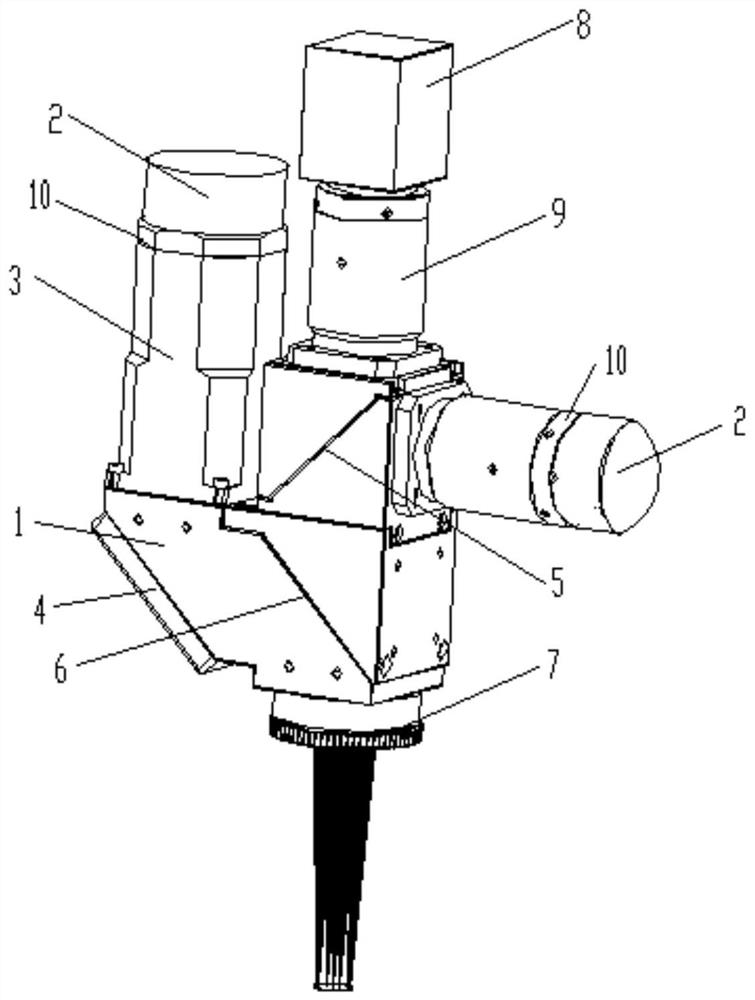
[0035] On the basis of the above-mentioned structure, in the present embodiment, the reflection assembly includes a total reflection mirror 4, a reflection mirror 5 and a light combining mirror 6, and the total reflection mirror 4 is tilted by means that those skilled in the art can think of such as gluing or bolting. The position below the corresponding input port 1 in the mounting seat 1 is used to reflect the laser beam input from the input port 1; the reflective mirror 5 is tilted and installed on the mounting seat 1 by means that those skilled in the art can imagine such as gluing or bolting The position close to the upper end of the mounting base 1 is used to reflect the laser beam input from the input port 2; the light combining mirror 6 is tilted and installed in the mounting base 1 by means that those skilled in the art can think of, such as gluing or bolting. The position of the lower end of the seat 1, and parallel to the total reflection mirror 4, is used to respect...

Embodiment 2

[0037] On the basis of Embodiment 1, in this embodiment, the mounting seat 1 is an L-shaped seat, the lower end of the vertical part is fixedly connected and communicated with one end of the horizontal part, and the lower through hole is located at the lower end of the vertical part; Formed integrally with the horizontal section. The first input port is located on the upper side of the other end of the horizontal part, and the second input port is located on one side of the upper end of the vertical part. The scheme is simple in structure, reasonable in design, convenient to install various components without mutual influence, and convenient to use.

Embodiment 3

[0039] On the basis of Embodiment 2, in this embodiment, the lower side of the other end of the horizontal part is slope-shaped and open, and the total reflection mirror 4 is fixedly installed on the open part of the horizontal part. The structure is simple, the design is reasonable, and it is convenient to install each part.

[0040] The reflecting mirror 5 and the light combining mirror 6 are located in the upper end and the lower end of the vertical portion respectively.


PUM


Abstract

The invention relates to an optical system integrating laser paint stripping and welding. The optical system comprises a mounting base, a reflection assembly and two lasers for paint stripping and welding of a weld assembly, the interior of the mounting base is hollow, and the lower end of the mounting base is provided with a lower through hole; a first input port is formed in one side of the mounting base in the vertical direction, and a second input port is formed in the other side of the mounting base in the horizontal direction; the two lasers are fixedly mounted at the first input port and the second input port respectively and used for emitting laser beams correspondingly. and the reflection assembly is fixedly mounted in the mounting base and used for reflecting the laser beams emitted by the two lasers so that any laser beam can be emitted out of the lower through hole. The optical system has the beneficial effects that the structure is compact, laser paint stripping and welding are integrated, paint stripping and welding of an inductance coil can be achieved, and the quality of paint stripping and welding of the inductance coil is guaranteed.

Description

technical field [0001] The invention relates to the technical field of laser welding, in particular to an optical system integrating laser paint stripping and welding. Background technique [0002] Paint stripping equipment is often used in related production processes such as inductance coils. At present, the traditional way is to use immersion tin to melt the paint skin through high temperature to achieve the purpose of stripping paint. However, this method is easy to damage the coil, and the yield rate is low. To ensure the quality of paint stripping; some others use strong corrosive agents to corrode the paint skin to achieve the purpose of peeling paint. This method also has certain damage to the inductance coil, and the yield rate is low. In addition, there is a physical paint stripping method, using mechanical props Carry out cutting and stripping paint, but this method can only carry out paint stripping treatment on coils with a wire diameter larger than 0.15mm. Co...

Claims


Application Information

Patent Timeline
IPC IPC(8): B23K26/06B23K26/064B23K26/21B23K26/36B23K26/70
Inventor 张聪张靖宇陈航陈绪兵章王子涵聂卫平方昕毅于宝成唐海波
Owner WUHAN INSTITUTE OF TECHNOLOGY
Learn More