
Dust removal equipment for feed processing

A technology for dust removal equipment and feed processing, which is applied in the separation of dispersed particles, chemical instruments and methods, and filtration of dispersed particles.

Pending Publication Date: 2021-04-20
无锡市昌顺科技有限公司
View PDF9 Cites 0 Cited by
  • Summary
  • Abstract
  • Description
  • Claims
  • Application Information

AI Technical Summary

Problems solved by technology

[0003] The current dust removal equipment for feed processing mainly filters the dust through the filter plate, and the accumulation of the filter at any time, the dust is easy to adhere to the filter plate, thus affecting the dust removal efficiency and dust removal effect, and the filter plate needs to be disassembled frequently during cleaning. troublesome, not practical

Method used


Image

  • Dust removal equipment for feed processing
  • Dust removal equipment for feed processing
  • Dust removal equipment for feed processing

Examples


Embodiment 1

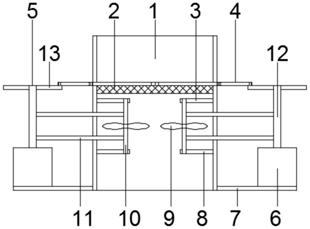
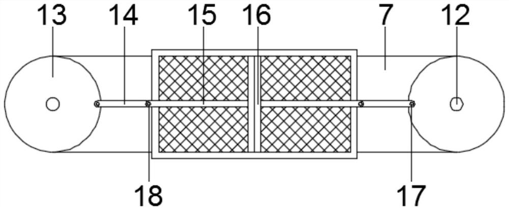
[0022] Such as figure 1 , 2 The shown dust removal equipment for feed processing includes a dust removal cylinder 1, a filter plate 2 is fixedly installed in the dust removal cylinder 1, a blower mechanism 3 is installed on one side of the filter plate 2, and a filter plate cleaning mechanism 4 is installed on the other side The outer side of the dust removal cylinder 1 is fixedly installed with a drive mechanism 5 for driving the blower mechanism 3 and the filter plate cleaning mechanism 4 to work, that is, the drive mechanism 5 is set to work with the blower mechanism 3 to filter the waste gas through the filter plate 2 and then discharge it. At the same time, the filter plate cleaning mechanism 4 is used to clean the filter plate 2, thereby effectively preventing the filter plate 2 from clogging and affecting the dust removal efficiency.

[0023] Further, the drive mechanism 5 includes a drive motor 6, and a motor mounting plate 7 fixedly connected to it is installed on th...

Embodiment 2

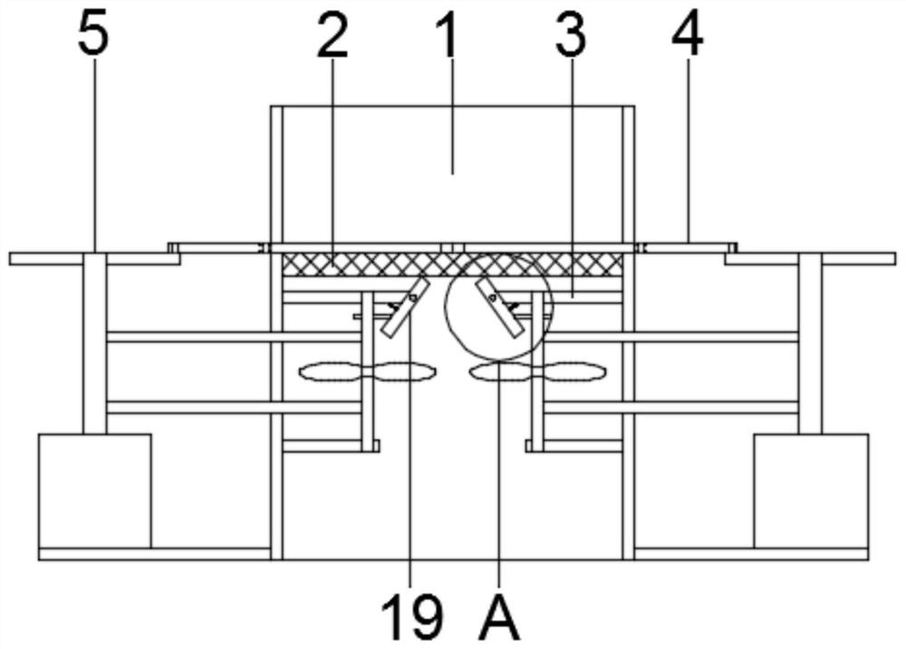
[0026] This embodiment is further optimized on the basis of Embodiment 1. A vibration mechanism 19 is installed on the blowing mechanism 3, that is, the filter plate 2 is knocked by the vibration mechanism 19, thereby further improving the cleaning effect. Specifically, the vibration Mechanism 19 includes a vibrating rod 21, which is arranged on the fan support 8 and is rotatably connected to it. A spring 22 fixedly connected to it is installed at the bottom of the vibrating rod 21. The end of the spring 22 away from the vibrating rod 21 is connected to the fan support. 8 is fixedly connected, and the outer fixed sleeve of the synchronous shaft 10 is provided with a cam 23 that matches the vibrating rod 21, that is, the synchronous shaft 10 rotates synchronously with the cam 23 when it rotates, and the lower end of the vibrating rod 21 is caused by the action of the spring 22 to make it The upper end is separated from the filter plate 2. When the cam 23 rotates to make the conv...


PUM


Abstract

The invention relates to dust removal equipment for feed processing, and belongs to the technical field of feed processing equipment. The dust removal equipment comprises a dust removal cylinder, a filter plate is fixedly mounted in the dust removal cylinder, an air blowing mechanism is mounted on one side of the filter plate, and a filter plate cleaning mechanism is mounted on the other side of the filter plate; and a driving mechanism for driving the air blowing mechanism and the filter plate cleaning mechanism to work is fixedly mounted on the outer side of the dust removal cylinder. The driving mechanism is arranged to drive the air blowing mechanism and the filter plate cleaning mechanism to work at the same time, blockage of the filter plate is effectively avoided while stable dust removal is achieved, and efficient and stable dust removal operation is guaranteed; meanwhile, the vibration mechanism is mounted on the air blowing mechanism, and the filter plate is continuously beaten in the blowing process, so filter plate clogging is further avoided, the dust removal effect is good, the dust removal efficiency is high, and the dust removal equipment is more convenient and practical.

Description

technical field [0001] The invention relates to the technical field of feed processing equipment, in particular to dust removal equipment for feed processing. Background technique [0002] Feed is the general term for the food of animals raised by all people. In a narrower sense, general feed mainly refers to the food of animals raised in agriculture or animal husbandry. The feed includes soybean, soybean meal, corn, fish meal, amino acid, miscellaneous meal, whey powder, oil, meat and bone meal, grains, feed additives and more than ten varieties of feed materials. A certain amount of dust will be generated during the feed processing process. In order to reduce the harm to the environment and human body, dust removal treatment is required. [0003] The current dust removal equipment for feed processing mainly filters the dust through the filter plate, and the accumulation of the filter at any time, the dust is easy to adhere to the filter plate, thus affecting the dust remo...

Claims


Application Information

Patent Timeline
IPC IPC(8): B01D46/10B01D46/00
Inventor 韩玲珑包夏东刘云珠
Owner 无锡市昌顺科技有限公司
Learn More