
Construction method and construction structure for preventing ground subsidence caused by backfill looseness under foundation straining beam

A ground subsidence and construction method technology, applied in the direction of infrastructure engineering, filling, construction, etc., can solve problems such as backfilling is not dense, achieve the effect of reasonable construction structure, ensure construction quality, improve economic performance and safety and reliability

Inactive Publication Date: 2021-04-16
SHANDONG SANJIAN CONSTR ENG +1
View PDF6 Cites 0 Cited by
  • Summary
  • Abstract
  • Description
  • Claims
  • Application Information

AI Technical Summary

Problems solved by technology

[0003] The invention provides a construction method and a construction structure for preventing ground subsidence caused by loose backfilling under the foundation tension beam, solves the above-mentioned problems existing in the prior art, and effectively solves the problem of ground subsidence caused by insufficient backfilling under the foundation tension beam, and at the same time Save costs and ensure quality

Method used


Image

  • Construction method and construction structure for preventing ground subsidence caused by backfill looseness under foundation straining beam
  • Construction method and construction structure for preventing ground subsidence caused by backfill looseness under foundation straining beam
  • Construction method and construction structure for preventing ground subsidence caused by backfill looseness under foundation straining beam

Examples


Embodiment 1

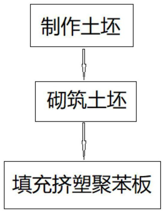
[0033] Construction methods to prevent ground subsidence caused by loose backfilling under foundation tension beams, such as figure 2 , including the following steps,

[0034] At the construction site, the adobe 1 is made by using a billet making machine;

[0035] Masonry the prepared adobe 1 under the foundation tension beam 2, and separate the space of the foundation tension beam 2;

[0036] Make the width of the adobe layer behind the masonry equal to the width of the foundation tension beam 2;

[0037] A gap of preset height is reserved between the bottom of the foundation tension beam 2 and the top of the adobe 1 , and the gap is filled with extruded polystyrene boards 3 .

[0038] Construction structures that prevent ground subsidence due to loose backfill under foundation tension beams, such as image 3 , it is constructed by the construction method of the present embodiment that prevents ground subsidence due to loose backfilling under the foundation tension beam. ...

Embodiment 2

[0040] The construction method to prevent ground subsidence due to loose backfilling under the foundation tension beam is similar to that of Example 1, the difference is that when the prepared adobe 1 is laid under the foundation tension beam 2, it is built from bottom to top and from the foundation One side below the tension beam 2 is built by laying bricks or stones to the other side.

[0041] Furthermore, in the construction method of this embodiment to prevent ground subsidence due to loose backfilling under the foundation tension beam, the prepared adobe 1 is built under the foundation tension beam 2, and the upper and lower adjacent two-layer adobe 1 Interval staggered seam distribution.

[0042] At this time, the construction structure to prevent ground subsidence due to loose backfill under the foundation tension beam is constructed through the construction method of this embodiment to prevent ground subsidence due to loose backfill under the foundation tension beam. F...


PUM


Abstract

The invention discloses a construction method and a construction structure for preventing ground subsidence caused by backfill looseness under a foundation straining beam. The construction method and the construction structure solve the problem of ground subsidence caused by narrow space under the foundation straining beam and incapability of tamping backfill soil. The construction method comprises the following steps that adobe is manufactured by utilizing an adobe manufacturing machine on a construction site; the manufactured adobe is built under the foundation straining beam, and the space of the foundation straining beam is separated; the width of the built adobe layer is enabled to be equal to that of the foundation straining beam; and in order to ensure that the stress mode of the foundation straining beam is not changed, a gap with a preset height is reserved between the bottom of the foundation straining beam and the top of the adobe, and the gap is filled with an extruded polystyrene board. According to the scheme, the construction structure is reasonable, the construction method is simple and convenient, local materials can be used for construction, cost is saved, efficiency is improved, construction quality is guaranteed, and economic performance and safe and reliable performance are improved.

Description

technical field [0001] The invention belongs to the technical field of building construction, and in particular relates to a construction method and a construction structure for preventing ground subsidence caused by loose backfill under foundation tension beams. Background technique [0002] Currently under construction, such as figure 1 , when the height of the bottom layer of the structure is high and the foundation is buried deep at the same time, in addition to setting the tension beam normally according to the code requirements, the structural frame beam is generally set at the appropriate position below ±0.000; however, the operating space of this part of the foundation tension beam is generally It is very narrow, and often the tamping machine cannot tamp it in place when backfilling the soil; as a result, the backfilling of the tension beams of the first floor foundation is not dense, resulting in ground subsidence after the construction of the first floor, causing v...

Claims


Application Information

Patent Timeline
Patent Type & Authority Applications(China)
IPC IPC(8): E02D27/00E02D17/18
Inventor 康照超梁园于茂娟胡晓波朱君田芮杨建龙陶明浩
Owner SHANDONG SANJIAN CONSTR ENG
Learn More