Modular embroidery machine

An embroidery machine, a modular technology, applied in the field of embroidery machines, can solve the problems that the strength of the main shaft cannot well meet the driving requirements of the embroidery machine, the shape of the embroidery body is increased, the size of the main shaft is limited, etc., and the transmission efficiency is improved and the structure is simple. , The effect of reducing the installation accuracy requirements

Pending Publication Date: 2021-04-16
ZHEJIANG XINSHENG SEWING EQUIP
View PDF0 Cites 0 Cited by
  • Summary
  • Abstract
  • Description
  • Claims
  • Application Information

AI Technical Summary

Problems solved by technology

In the existing embroidery machine structure, due to the setting of the main shaft through the machine head, the size of the main shaft is limited, and the strength of the main shaft cannot well meet the driving requirements of the embroidery machine
If the strength of the main shaft is increased by increasing the outer diameter of the main shaft, in order to reserve enough installation space, the overall size of the machine head must also be increased accordingly, and the shape of the embroidery machine will also increase accordingly, which is not conducive to controlling production. cost
In addition, when the main shaft is deformed or broken and needs to be replaced, the needle bar driving mechanism and presser foot driving mechanism on all machine heads need to be separated from the main shaft, which makes maintenance more complicated.

Method used


Image

  • Modular embroidery machine
  • Modular embroidery machine
  • Modular embroidery machine

Examples


Embodiment 1

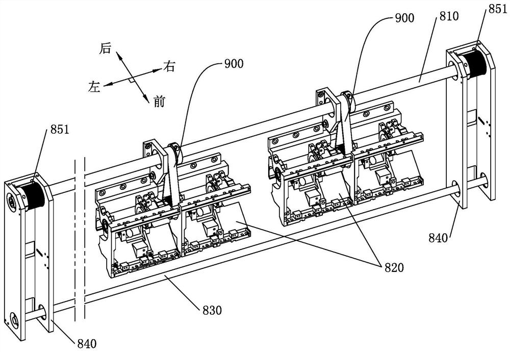
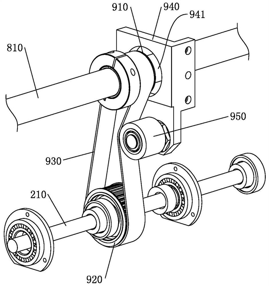
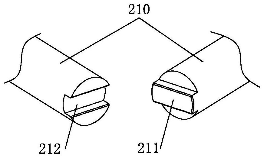
[0033] Such as figure 1 , figure 2 As shown, the present invention provides a modular embroidery machine, including a horizontal main shaft 810, a main drive motor for driving the main shaft 810, and a plurality of machine head modules 820 arranged at intervals along the transverse direction, and the main shaft 810 is arranged on each machine head Outside the modules 820 , each head module 820 is provided with a horizontal needle bar drive shaft 210 , and a split drive transmission mechanism 900 is provided between the needle bar drive shaft 210 and the main shaft 810 of each head module 820 .

[0034] Since the main shaft is located outside the head module, the strength of the main shaft can be increased by increasing the outer diameter of the main shaft to better meet the structural requirements of the embroidery machine. The internal installation space of the head will be affected. When the main shaft needs to be replaced, it is only necessary to disassemble the relevant...


PUM


Abstract

The invention discloses a modular embroidery machine, and belongs to the technical field of embroidery machines. The modular embroidery machine comprises a transversely arranged main shaft and a main driving motor for driving the main shaft, and further comprises a plurality of machine head modules which are arranged at intervals along the transverse direction, wherein a main shaft is arranged outside each machine head module, each machine head module is provided with a transversely arranged needle rod driving shaft, and a sub-drive transmission mechanism is arranged between the needle rod driving shaft of each machine head module and the main shaft. Due to the fact that the main shaft is arranged outside the machine head module, the strength of the main shaft can be improved by increasing the outer diameter of the main shaft, the structural requirement of the embroidery machine is better met, and the change of the outer diameter of the main shaft is prevented from influencing the boundary dimension of the machine head and the inner installation space of the machine head. When the main shaft needs to be replaced, only related components of the sub-drive transmission mechanism need to be detached from the main shaft, and components on the machine head module do not need to be detached, so that the number of the components needing to be detached is greatly reduced, maintenance difficulty is lowered, and maintenance efficiency is improved.

Description

technical field [0001] The invention relates to the technical field of embroidery machines, in particular to a modular embroidery machine. Background technique [0002] With the advancement of science and technology, computerized embroidery machines have now become the main mechanical equipment in the embroidery industry, and the head of the embroidery machine is an important structure of the embroidery machine. In the existing embroidery machine structure, a main shaft passes through all the machine heads to provide power for the needle bar drive and the presser foot drive on each machine head. With the improvement of market demand, the number of heads on the embroidery machine continues to increase, so the rigidity requirements for the main shaft are also getting higher and higher. In the existing embroidery machine structure, due to the setting of the main shaft passing through the machine head, the size of the main shaft is limited, and the strength of the main shaft ca...

Claims


Application Information

Patent Timeline
Patent Type & Authority Applications(China)
IPC IPC(8): D05C11/06
Inventor 王海江田桂郁
Owner ZHEJIANG XINSHENG SEWING EQUIP
Why Eureka
Try Eureka