Roller type optical detection equipment

An optical detection and equipment technology, applied in the field of roller-type optical detection equipment, can solve the problems of low detection efficiency of cylindrical workpieces, and achieve the effect of convenient detection and improved detection efficiency

Pending Publication Date: 2021-04-16
嘉兴罗思科技有限公司
View PDF0 Cites 1 Cited by
  • Summary
  • Abstract
  • Description
  • Claims
  • Application Information

AI Technical Summary

Problems solved by technology

[0003] In view of the above-mentioned related technologies, the inventor believes that the detection efficiency of the cylindrical workpiece is low in the above-mentioned detection method

Method used


Image

  • Roller type optical detection equipment
  • Roller type optical detection equipment
  • Roller type optical detection equipment

Examples


Embodiment Construction

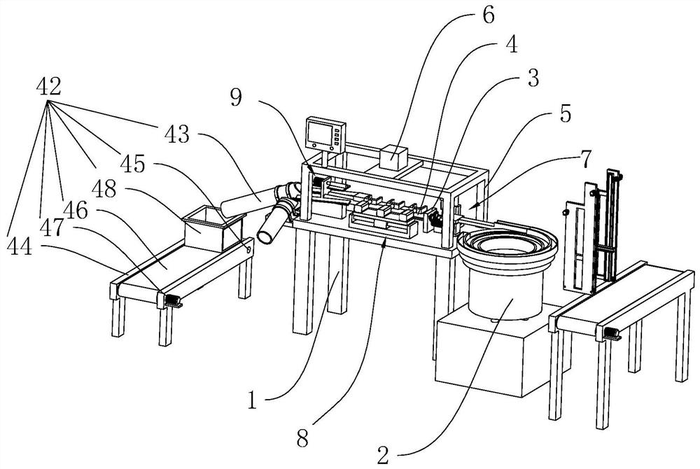
[0031] The following is attached Figure 1-4 The application is described in further detail.

[0032] The embodiment of the present application discloses a roller type optical detection device.

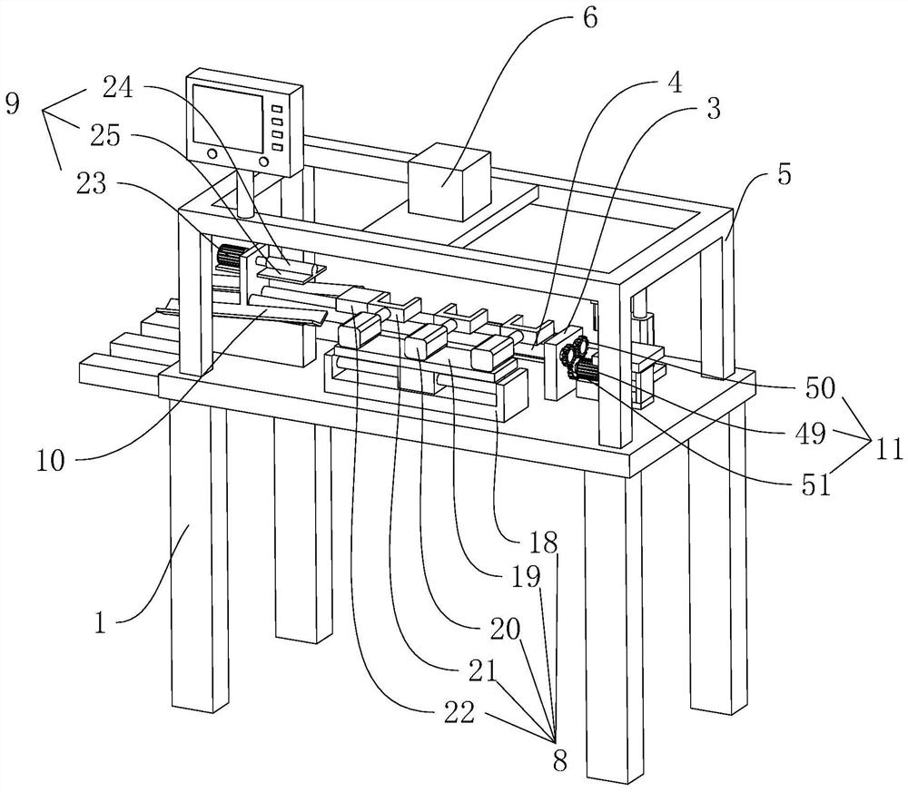
[0033] Such as figure 1 , figure 2 As shown, the roller-type optical detection equipment includes a detection table 1 arranged in a rectangular shape, and a vibrating plate 2 is arranged on one end of the detection table 1. Materials are placed in the vibrating plate 2. There is a vertical plate 3 fixedly connected, and two circular shafts 4 are rotatably connected between the two vertical plates 3. The two circular shafts 4 are arranged in gaps and are on the same horizontal plane. A line-scanning camera 6 with a high frame rate is fixedly connected to the bracket 5 , and a driving member 11 for driving two circular shafts 4 to rotate in the same direction is provided on the detection table 1 .

[0034] As shown in Figure 2, the driving member 11 includes a driving motor 49 fixe...


PUM


Abstract

The invention relates to roller type optical detection equipment. The equipment comprises a detection table, a vibration disc is arranged at one end of the detection table, vertical plates are fixedly connected to the two ends of the detection table, a circular shaft is rotatably connected between the two vertical plates, a support is fixedly connected to the upper surface of the detection table, a line scanning camera is fixedly connected to the support, and a feeding mechanism is arranged on the upper surface of one end of the detection table. A driving mechanism is arranged on the detection table, a sorting mechanism is arranged on the vertical plate away from the vibration disc, two discharging sliding ways are fixedly connected to one end of the detection table, a driving piece is arranged on the upper surface of the detection table, a workpiece is placed in the vibration disc, the workpiece is driven out through the vibration disc, and the workpiece is carried to the circular shaft through the feeding mechanism. The driving mechanism drives the workpiece to move on the circular shaft, the driving piece drives the workpiece to rotate, the outer wall of the workpiece is scanned through the line scanning camera, the workpiece is sorted through the sorting mechanism, detection of the arc-shaped workpiece is facilitated, and the detection efficiency of the cylindrical workpiece is improved.

Description

technical field [0001] The present application relates to a detection device, in particular to a roller type optical detection device. Background technique [0002] Cylindrical workpieces are often encountered in the existing processing and production. For these cylindrical workpieces in the detection process, the existing detection usually requires the operator to manually detect one by one. [0003] With regard to the above-mentioned related technologies, the inventor believes that the detection efficiency of the cylindrical workpiece is low in the above-mentioned detection method. Contents of the invention [0004] In order to improve detection efficiency, the present application provides a roller-type optical detection device. [0005] The roller-type optical detection equipment provided by this application adopts the following technical scheme: [0006] A roller-type optical detection equipment, including a detection table, a vibrating plate is arranged on one end o...

Claims


Application Information

Patent Timeline
Patent Type & Authority Applications(China)
IPC IPC(8): B07C5/342
Inventor 郭峰平
Owner 嘉兴罗思科技有限公司
Why Eureka
Try Eureka