
Orthopaedic retractor and orthopaedic surgery assembly

An orthopedic surgery and retractor technology, applied in the field of medical devices, can solve problems such as disadvantage, less adjustable angle, disadvantageous surgical operation, etc., and achieve the effects of simple structure, improved speed, and high convenience of assembly.

Pending Publication Date: 2021-04-16
赖宗权
View PDF1 Cites 0 Cited by
  • Summary
  • Abstract
  • Description
  • Claims
  • Application Information

AI Technical Summary

Problems solved by technology

[0003] The Chinese patent discloses orthopedic retractors and orthopedic surgical components (authorized announcement number CN211094367U). This patented technology often uses drainage tubes and cold light sources during surgery. These tubes often block the surgical field of view during surgery and affect the surgical effect. , the quality of surgery cannot be guaranteed. However, the orthopedic retractors and orthopedic surgical components currently on the market generally hinder the operation line of sight after installation, which is not conducive to surgical operations. Generally, the adjustable angle of the device is less, which is not conducive to the device. The flexibility of use, the convenience of assembly of general devices is low, which is not conducive to the speed of surgical operations, the general device can not adjust the support angle, and the placement angle of the support feet of the support frame is not conducive to the placement of support feet

Method used


Image

  • Orthopaedic retractor and orthopaedic surgery assembly
  • Orthopaedic retractor and orthopaedic surgery assembly
  • Orthopaedic retractor and orthopaedic surgery assembly

Examples


Embodiment Construction

[0022] The following will clearly and completely describe the technical solutions in the embodiments of the present invention with reference to the accompanying drawings in the embodiments of the present invention. Obviously, the described embodiments are only some, not all, embodiments of the present invention. Based on the embodiments of the present invention, all other embodiments obtained by persons of ordinary skill in the art without making creative efforts belong to the protection scope of the present invention.

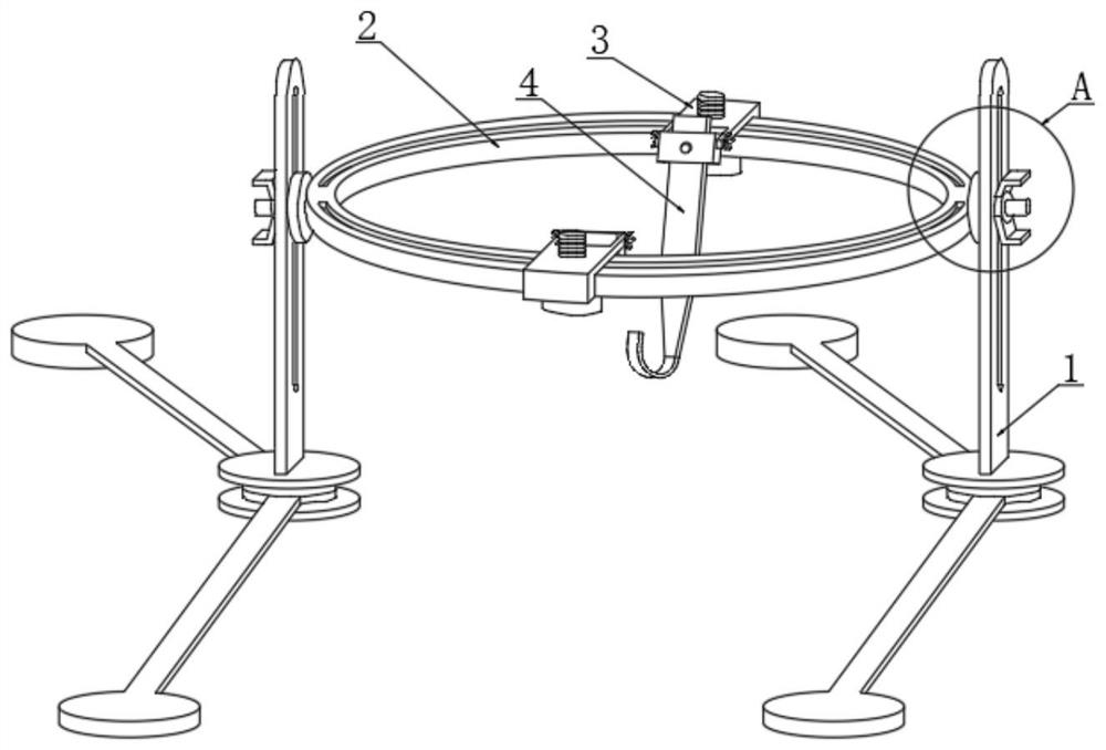
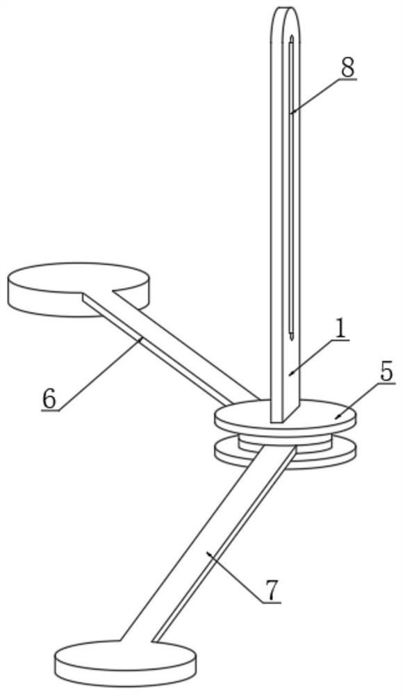
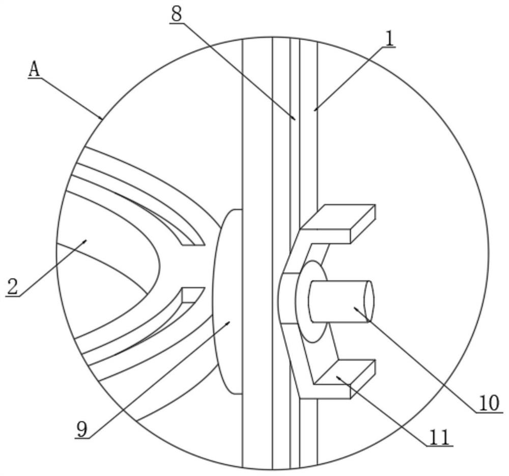
[0023] see Figure 1-6 , in the embodiment of the present invention, the retractor for orthopedics and the orthopedic surgery assembly include a support frame 1, a support ring 2 is installed on the upper inner side of the support frame 1, a retractor installation structure 3 is installed on the upper surface of the support ring 2, and the support frame 1 The lower end is welded with a foot plate 5, the inside of the foot plate 5 is rotated with a first suppor...


PUM


Abstract

The invention relates to the technical field of medical instruments, in particular to an orthopaedic retractor and orthopaedic surgery assembly. The orthopaedic retractor and orthopaedic surgery assembly comprises a support frame, wherein a support ring is mounted at the upper end of the upper inner side of the support frame, a retractor mounting structure is mounted on the upper surface of the support ring, a foot plate is welded to the lower end of the support frame, a first support leg is rotatably mounted in the foot plate, a second supporting leg is rotatably mounted on the lower surface of the first supporting leg in the foot disc, a retractor clamping block is rotatably mounted at the front end of the retractor mounting structure, a retractor is mounted in the retractor clamping block, a sliding groove is formed in one side of the supporting frame, limiting seats are welded to the outer surfaces of the two sides of the supporting ring, and an adjusting screw rod is welded to one side of each limiting seat. The orthopaedic retractor and orthopaedic surgery assembly is of a ring type supporting structure, cannot block the operation sight of an operation in the using process, can be adjusted at multiple angles, is simple in structure, can adjust the supporting placement angle of the supporting leg, and facilitates placement of the supporting leg.

Description

technical field [0001] The invention relates to the technical field of medical devices, in particular to orthopedic retractors and orthopedic surgical components. Background technique [0002] Medical devices refer to instruments, equipment, utensils, in vitro diagnostic reagents and calibrators, materials, and other similar or related items that are directly or indirectly used on the human body, including the required computer software. The utility is mainly obtained through physical means, not through Pharmacological, immunological or metabolic means, or although these means are involved, they only play an auxiliary role. [0003] The Chinese patent discloses orthopedic retractors and orthopedic surgical components (authorized announcement number CN211094367U). This patented technology often uses drainage tubes and cold light sources during surgery. These tubes often block the surgical field of view during surgery and affect the surgical effect. , the quality of surgery c...

Claims


Application Information

Patent Timeline
Patent Type & Authority Applications(China)
IPC IPC(8): A61B17/02
Inventor 赖宗权
Owner 赖宗权
Learn More