
Optical fiber monitoring system for transformer substation

A substation and optical fiber technology, applied in the field of smart substations, can solve the problems of optical fiber link failure, inability to monitor and protect primary equipment, and affect data transmission of secondary equipment, etc., to achieve the effect of reducing the impact

Pending Publication Date: 2021-04-13
国网宁夏电力有限公司固原供电公司
View PDF2 Cites 0 Cited by
  • Summary
  • Abstract
  • Description
  • Claims
  • Application Information

AI Technical Summary

Problems solved by technology

[0003] However, in practical applications, due to the fiber material and other reasons, the fiber link will fail
Once the optical fiber link fails, it will inevitably affect the data transmission between these secondary equipment, and then the dispatching end of the substation cannot monitor and protect the primary equipment monitored by the secondary equipment.

Method used


Image

  • Optical fiber monitoring system for transformer substation
  • Optical fiber monitoring system for transformer substation
  • Optical fiber monitoring system for transformer substation

Examples


Embodiment Construction

[0032] In the following description, numerous specific details are set forth in order to provide a thorough understanding of the application. However, the present application can be implemented in many other ways different from those described here, and those skilled in the art can make similar promotions without violating the connotation of the present application. Therefore, the present application is not limited by the specific implementation disclosed below.

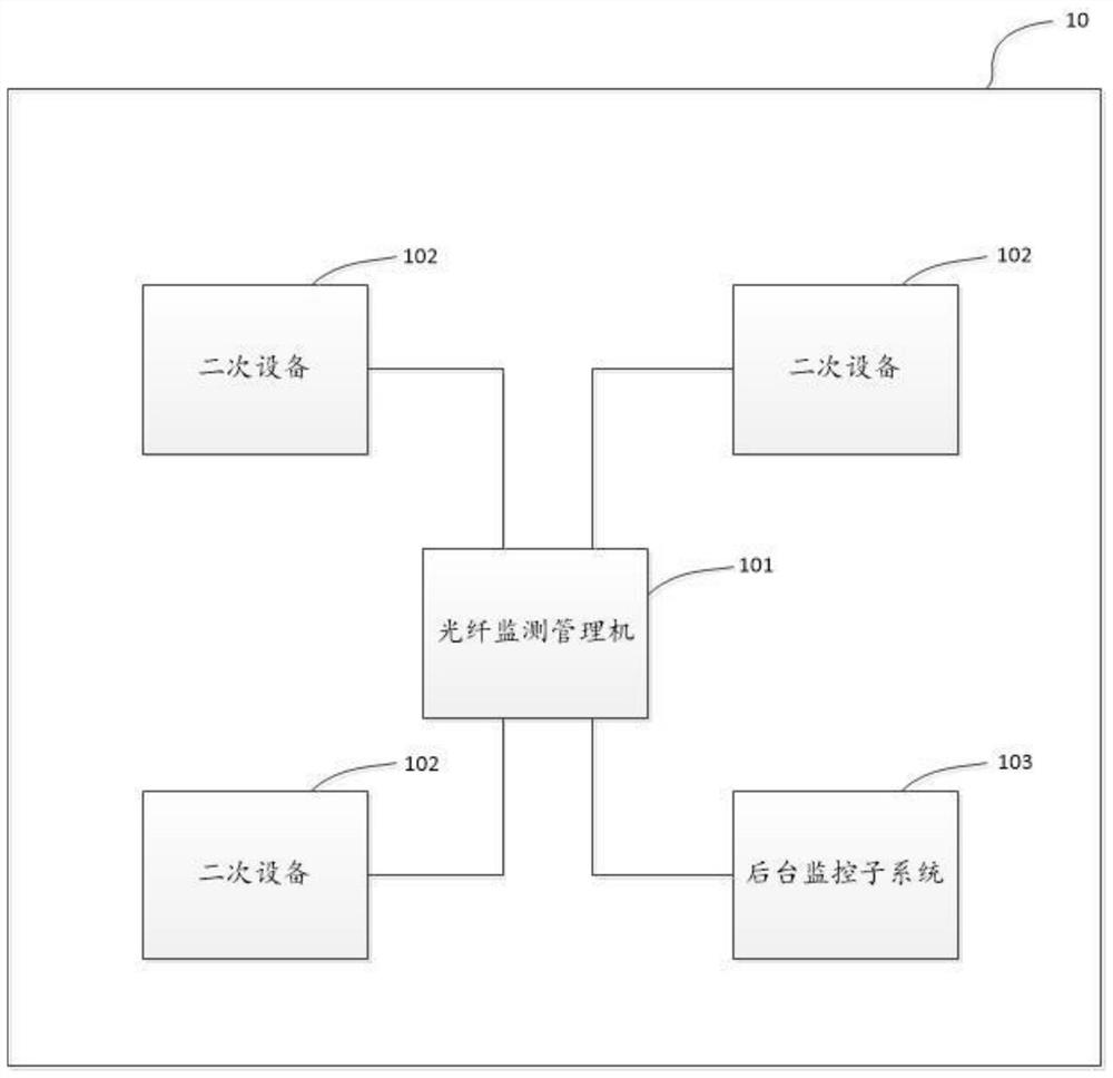
[0033] An embodiment of the present application provides an optical fiber monitoring system for a substation. For ease of understanding, first a brief description will be given of the actual application scenario of the optical fiber monitoring system in the substation.

[0034] In practical applications, transformers are the core of substations. Due to the influence of many factors, it is easy to cause a series of faults, which in turn affect the normal power supply of substations, and even lead to large-scale power ...


PUM


Abstract

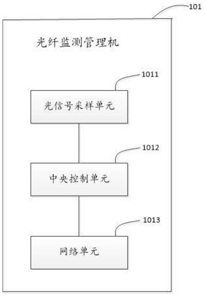
The embodiment of the invention provides an optical fiber monitoring system for a transformer substation. The system comprises an optical fiber monitoring management machine, a background monitoring subsystem, and a plurality of secondary devices in the transformer substation, the optical fiber monitoring management machine is connected with each secondary device in the plurality of secondary devices through an optical fiber, and the optical fiber monitoring management machine is connected with the background monitoring subsystem; the optical fiber monitoring management machine is used for monitoring an optical signal attenuation state between every two secondary devices in the plurality of secondary devices; and the background monitoring subsystem is used for judging whether optical fiber signal transmission between the secondary equipment fails or not according to the optical signal attenuation state information. According to the embodiment of the invention, the monitoring of the optical fiber link between the secondary equipment in the transformer substation is realized, and the fault of the optical fiber link can be found in time.

Description

technical field [0001] The present application relates to the technical field of smart substations, in particular to an optical fiber monitoring system for substations. Background technique [0002] The smart substation is constructed by layers of intelligent primary equipment and networked secondary equipment. The primary equipment mainly realizes the functions of power generation, transmission, and distribution of the substation. Information sharing and interoperability between the primary equipment and the secondary equipment in the substation, and data transmission between these secondary equipment through optical fiber. [0003] However, in practical applications, due to reasons such as the material of the optical fiber, the optical fiber link may fail. Once the optical fiber link fails, it will inevitably affect the data transmission between these secondary devices, which will cause the dispatching end of the substation to be unable to monitor and protect the primary ...

Claims


Application Information

Patent Timeline
Patent Type & Authority Applications(China)
IPC IPC(8): H02J13/00
CPCH02J13/00017Y04S10/16Y04S40/124Y02E60/00
Inventor 付强马文浩卢刚刚苏玉忠陈远高雯赵通汉赵志东马嘉马强
Owner 国网宁夏电力有限公司固原供电公司
Learn More