
Aerial oblique photography device

An oblique photography and aviation technology, which is applied in the directions of measuring devices, photographing devices, photogrammetry/video metrology, etc., can solve the problems of poor self-locking effect of steering gear, lack of automatic scraping structure, and reducing the photography effect of aerial photography devices, etc. , to achieve the effect of improving reliability and improving photographic effect

Inactive Publication Date: 2021-04-13
杨明
View PDF1 Cites 2 Cited by
  • Summary
  • Abstract
  • Description
  • Claims
  • Application Information

AI Technical Summary

Problems solved by technology

[0005] In order to solve the above-mentioned technical problems, the present invention provides an aerial tilting photography device to solve the problem that when the existing aerial photography device adjusts the tilt angle at the bottom of the drone, it is generally adjusted through the steering gear, and due to the self-locking effect of the steering gear It is poor, especially when the steering gear is powered off, it does not have self-locking performance, which reduces the reliability of the aerial photography device when it is used at the bottom of the drone, and the lens of the existing aerial photography device lacks an effective automatic scraping structure. , when water droplets appear on the front surface of the lens of the aerial photography device, they cannot be scraped off in time, thereby reducing the problem of the photographic effect of the aerial photography device

Method used


Image

  • Aerial oblique photography device
  • Aerial oblique photography device
  • Aerial oblique photography device

Examples


Embodiment

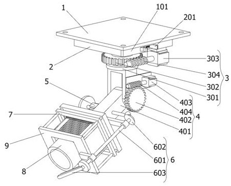
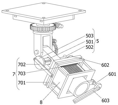
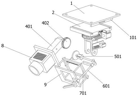
[0032] as attached figure 1 to attach Figure 7 Shown:

[0033] The present invention provides an aerial oblique photography device, which includes: a top plate 1, which is connected to the bottom of an external drone through bolts, the top plate 1 includes an L-shaped clamping plate 101, and four angles on the upper end surface of the top plate 1 are provided with It is installed, and the bottom end surface of the top plate 1 is fixedly connected with an L-shaped clamping plate 101, the right end surface of the L-shaped clamping plate 101 is provided with a rectangular bayonet, and the left bottom end surface of the L-shaped clamping plate 101 is symmetrically provided with two A T-shaped slide bar; a mounting part 2 is installed on the bottom surface of the top plate 1, and the mounting part 2 includes an elastic buckle 201 and a rectangular chute 202. There is a rectangular chute 202 in the middle of the right end surface of the part 2, and a partition plate is provided o...


PUM


Abstract

The invention provides an aerial oblique photography device, belongs to the technical field of aerial photography devices, and aims to solve the problem that when water drops appear on the front end surface of a lens of an existing aerial photography device, the water drops cannot be scraped off in time, so that the photography effect of the aerial photography device is reduced. The aerial oblique photography device comprises a top plate, and the top plate is connected to the bottom of an external unmanned aerial vehicle through bolts; a mounting piece is mounted on the bottom end surface of the top plate; a rotary adjusting piece is arranged at the bottom of the mounting piece; and the lower end of the rotary adjusting piece is rotationally connected with an angle adjusting piece. The aerial oblique photography device has the beneficial effects that a driving motor is started through flight control on the external unmanned aerial vehicle, so that a rotating shaft of the driving motor drives a first bevel gear to rotate, then a transmission shaft is driven by a second bevel gear to rotate, a rotating rod at the front end of the transmission shaft rotates on the front side of a camera body lens, and then the dew on the front end surface of the camera body lens is scraped by a rubber scraping strip on the rotating rod, so that the photographing effect of the aerial photographing device is improved.

Description

technical field [0001] The invention belongs to the technical field of aerial photography devices, and more specifically relates to an aerial oblique photography device. Background technique [0002] Aerial photography is also called "aerial photography". It refers to the way of taking pictures of ground or air targets from the air by using a special aerial camera installed on the aircraft. According to different photography objectives and directions, it can be divided into vertical photography, oblique photography and aerial photography. It can reduce the amount of field work, reduce labor intensity, and is not limited by geographical environment conditions, and has the advantages of fast, accurate, and economical. Widely used in surveying and mapping maps, geology, hydrology, mineral deposits and forest resource investigations, agricultural output evaluation and planning of large-scale factories, mines and towns, survey and selection of railways, highways, high-voltage t...

Claims


Application Information

Patent Timeline
Patent Type & Authority Applications(China)
IPC IPC(8): F16M11/04F16M11/12F16M11/18F16M13/02B64D47/08B08B1/00B08B1/04B08B11/00G01C11/00G01C11/02
CPCF16M11/04F16M11/12F16M11/18F16M13/02B08B11/00G01C11/00G01C11/02B64D47/08B08B1/165B08B1/30B08B1/32B08B1/12
Inventor 杨明徐华君许志圣
Owner 杨明
Learn More