
Monitoring equipment with power generation function

A technology for monitoring equipment and functions, applied in the field of monitoring equipment, can solve the problems of consuming large mineral resources, unfavorable energy saving and environmental protection, polluting the environment, etc., and achieve the effect of obvious effect, improved power generation effect, and good power generation effect.

Inactive Publication Date: 2021-04-13
江苏直播时代科技有限公司
View PDF0 Cites 2 Cited by
  • Summary
  • Abstract
  • Description
  • Claims
  • Application Information

AI Technical Summary

Problems solved by technology

[0003] The monitoring system generally monitors by setting up cameras outdoors. The cameras generally use electric energy as the driving source to operate. The existing electric energy is generally generated by coal, which consumes a large amount of mineral resources and pollutes the environment, which is not conducive to energy conservation and environmental protection. Therefore, the market Monitoring equipment that uses solar energy to generate electricity has appeared on the Internet, and the use of solar energy to generate electricity requires sufficient sunlight to achieve better power generation effects. Once the monitoring area is located in a dark area, or in an area with sufficient rain, use solar energy power generation is not applicable

Method used


Image

  • Monitoring equipment with power generation function
  • Monitoring equipment with power generation function
  • Monitoring equipment with power generation function

Examples


Embodiment Construction

[0025] The present invention is described in further detail now in conjunction with accompanying drawing. These drawings are all simplified schematic diagrams, which only illustrate the basic structure of the present invention in a schematic manner, so they only show the configurations related to the present invention.

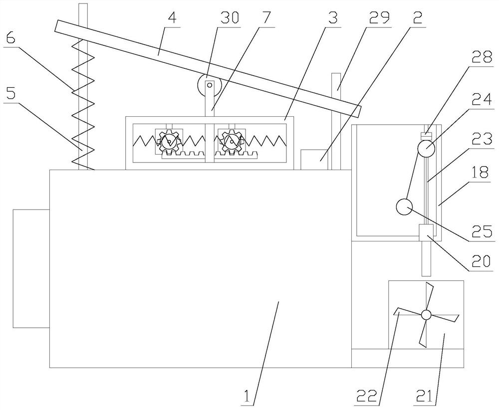
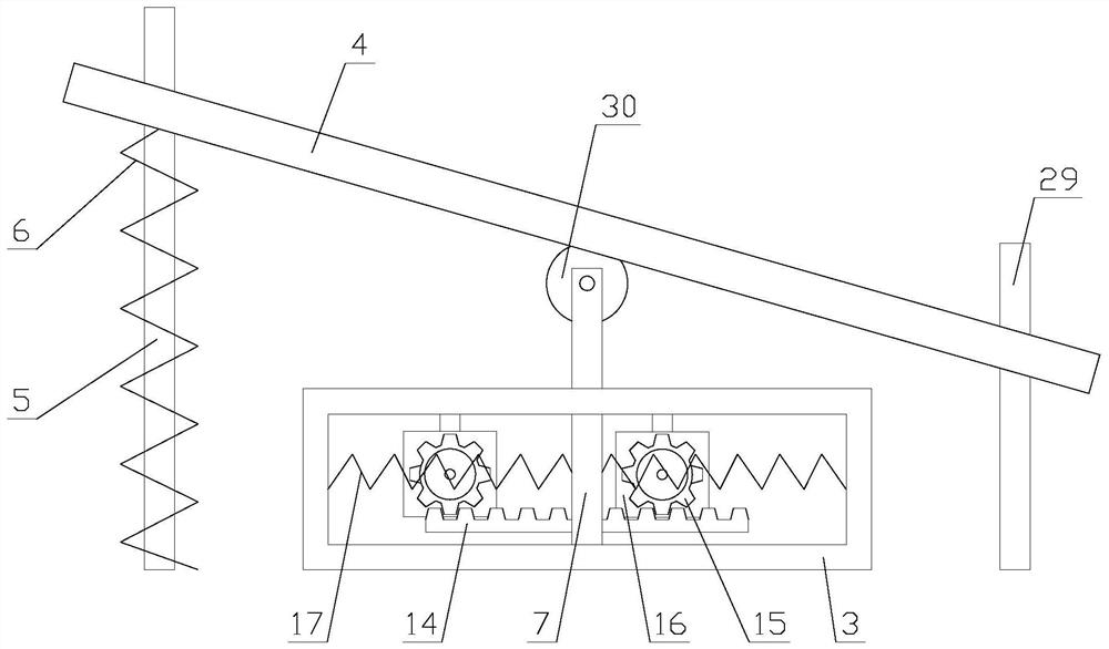
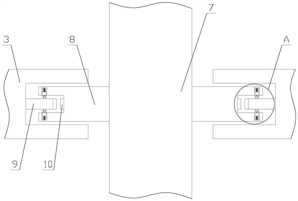
[0026] like figure 1 As shown, a monitoring device with power generation function includes a main body 1, a storage battery 2, a vibration power generation mechanism and a hydroelectric power generation mechanism. side of the institution;

[0027] When the device is in use, the main body 1 is operated to realize monitoring. When it rains, the rainwater hits the vibration generating mechanism to generate vibration, thereby realizing power generation. By accumulating rainwater, the hydroelectric generating mechanism is driven to realize hydroelectric power generation, and the vibration generating mechanism and hydroelectric power generation are realized. The e...


PUM


Abstract

The invention relates to monitoring equipment with a power generation function. The equipment comprises a main body, a storage battery, a vibration power generation mechanism, and a hydroelectric generation mechanism; and the hydroelectric generation mechanism is arranged at one side of the vibration power generation mechanism. The monitoring equipment with the power generation function achieves monitoring by operating the main body; the vibration power generation mechanism is operated by impacting a pressing plate through rainwater, so that power generation is achieved; and a water wheel is impacted by the rainwater, so that hydraulic power generation is achieved. Compared with an existing vibration power generation mechanism, the vibration power generation mechanism can reduce friction force generated when a pressing rod moves through a stabilizing assembly, so that the pressing rod moves more stably, the effect that the rainwater impacts the pressing plate is more obvious, and therefore the better power generation effect is achieved; and compared with an existing hydroelectric generation mechanism, the hydroelectric generation mechanism can enable the water wheel to be continuously impacted by water flow to rotate within a period of time through the process of storing water and then continuously draining water, so that a second power generator can efficiently and continuously operate for a period of time, and the power generation effect is improved.

Description

technical field [0001] The invention relates to a monitoring device with power generation function. Background technique [0002] The monitoring system is one of the most widely used systems in the security system. The most suitable construction site monitoring system on the market is a handheld video communication device. Video monitoring is now the mainstream. From the earliest analog monitoring to digital monitoring to the current network video monitoring, Earth-shaking changes have taken place. [0003] The monitoring system generally monitors by setting up cameras outdoors. The cameras generally use electric energy as the driving source to operate. The existing electric energy is generally generated by coal, which consumes a large amount of mineral resources and pollutes the environment, which is not conducive to energy conservation and environmental protection. Therefore, the market Monitoring equipment that uses solar energy to generate electricity has appeared on th...

Claims


Application Information

Patent Timeline
Patent Type & Authority Applications(China)
IPC IPC(8): F03B1/00F03B11/00F03B13/00F03G7/08H04N7/18
CPCF03B1/00F03B11/00F03B13/00F03G7/08H04N7/18Y02E10/20
Inventor 黄修海
Owner 江苏直播时代科技有限公司
Learn More