Lathe auxiliary device with functions of workpiece falling prevention and waste treatment

A waste treatment and auxiliary device technology, which is applied in metal processing machinery parts, metal processing, manufacturing tools, etc., can solve the problems of reducing cutting efficiency, affecting cutting operations, scratches, etc., to improve cutting efficiency, facilitate recycling, reduce The effect of production costs

Inactive Publication Date: 2021-04-13
南京晋亿达智能技术有限公司
View PDF0 Cites 0 Cited by
  • Summary
  • Abstract
  • Description
  • Claims
  • Application Information

AI Technical Summary

Problems solved by technology

[0002] A large amount of waste materials such as cutting fluid and chips will be produced during metal cutting. The machine tool in the prior art lacks a device for disposing of these waste materials, resulting in the accumulation of a large amount of metal chips on the workbench, which affects the cutting operation. After the cutting is completed, the machine tool needs to be cleaned manually, which increases The workload of the operators is reduced, and the cutting efficiency is reduced. Moreover, the cutting fluid mixed with chips cannot be discharged directly due to its pollution, so it needs to be separated and recycled. In addition, the existing workpieces will fall directly on the On the workbench, this is prone to damage to the workpiece and scratches on the surface

Method used


Image

  • Lathe auxiliary device with functions of workpiece falling prevention and waste treatment
  • Lathe auxiliary device with functions of workpiece falling prevention and waste treatment
  • Lathe auxiliary device with functions of workpiece falling prevention and waste treatment

Examples


Embodiment Construction

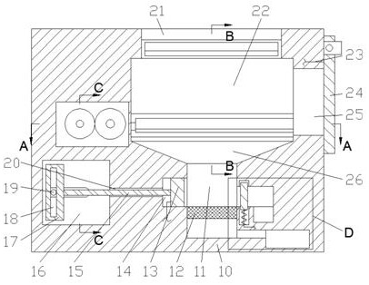
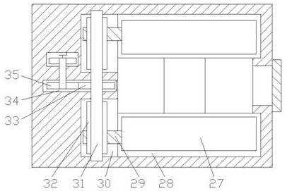
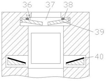
[0017] Combine below Figure 1-5 The present invention is described in detail, wherein, for the convenience of description, the orientations mentioned below are defined as follows: figure 1 The up, down, left, right, front and back directions of the projection relationship itself are the same.

[0018] A lathe auxiliary device with the functions of preventing workpiece from falling and waste material treatment described in conjunction with accompanying drawings 1-5 includes a main box body 10, and a working chamber 22 is arranged inside the main box body 10, and the working chamber 22 The lower end wall is connected with a collection chamber 26, and the lower end wall of the collection chamber 26 is connected with a filter chamber 11, and the left end wall of the filter chamber 11 is connected with a push plate chamber 14, and the push plate chamber 14 is slidingly fitted and connected with a cleaning chamber. Push plate 13, the left side of described push plate cavity 14 is ...


PUM


Abstract

The invention relates to the related field of metal cutting, and discloses a lathe auxiliary device with the functions of workpiece falling prevention and waste treatment. The lathe auxiliary device comprises a main box body, and a working cavity is formed in the main box body; a collecting cavity communicates with the lower end wall of the working cavity, and a filtering cavity communicates with the lower end wall of the collecting cavity; a push plate cavity communicates with the left end wall of the filtering cavity; a cleaning push plate is connected with the interior of the push plate cavity in a sliding fit mode, and a sliding plate cavity is formed in the left side of the push plate cavity; when a workpiece is cut, cutting components in cutting fluid are filtered out through a sieve plate; meanwhile, cuttings remaining on the sieve plate are continuously cleaned through reciprocating motion of the cleaning push plate, and therefore the situation that the sieve plate is blocked and consequently the filtering effect is influenced is avoided; the workload of waste treatment is reduced; the cutting efficiency is improved, and meanwhile the cutting fluid and the cuttings are separated, thereby facilitating subsequent recycling treatment; the production cost is reduced; after a workpiece is cut, a buffer plate is moved so that the workpiece falls onto the buffer plate, and the situation that the workpieces directly falls and is damaged is avoided; and meanwhile, the surface of the workpiece is prevented from being scratched.

Description

technical field [0001] The invention relates to the related fields of metal cutting, in particular to a lathe auxiliary device with the functions of preventing workpieces from falling and processing waste materials. Background technique [0002] A large amount of waste materials such as cutting fluid and chips will be produced during metal cutting. The machine tool in the prior art lacks a device for disposing of these waste materials, resulting in the accumulation of a large amount of metal chips on the workbench, which affects the cutting operation. After the cutting is completed, the machine tool needs to be cleaned manually, which increases The workload of the operators is reduced, and the cutting efficiency is reduced. Moreover, the cutting fluid mixed with chips cannot be discharged directly due to its pollution, so it needs to be separated and recycled. In addition, the existing workpieces will fall directly on the On the workbench, this can easily cause damage to the...

Claims


Application Information

Patent Timeline
Patent Type & Authority Applications(China)
IPC IPC(8): B23Q11/10B23Q7/00B23B15/00
CPCB23Q7/00B23Q11/1069
Inventor 高鹏星
Owner 南京晋亿达智能技术有限公司
Why Eureka
Try Eureka