
Automatic hoop locking equipment

An automatic lock and clamp technology, applied to other manufacturing equipment/tools, manufacturing tools, etc., can solve problems such as low work efficiency, different shapes, and inconformity with high-efficiency and low-cost production methods, and achieve the effect of improving production efficiency

Pending Publication Date: 2021-04-13
ZHEJIANG TELFORD PRECISION DRIVE MFG CO LTD
View PDF0 Cites 0 Cited by
  • Summary
  • Abstract
  • Description
  • Claims
  • Application Information

AI Technical Summary

Problems solved by technology

[0002] There are many models and different styles of the existing drive shaft assembly. When installing the clamp, the assembly is more complicated due to the different types and shapes.
When installing the locking clamp, the assistance of the staff is required, the work efficiency is low, the labor cost is high, and it does not meet the high-efficiency and low-cost production method

Method used


Image

  • Automatic hoop locking equipment
  • Automatic hoop locking equipment
  • Automatic hoop locking equipment

Examples


Embodiment Construction

[0030] The present invention will be described in further detail below in conjunction with the embodiments given in the accompanying drawings.

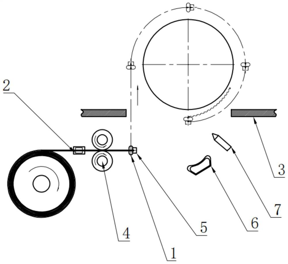
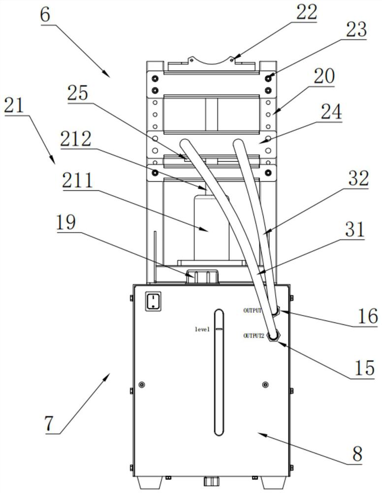
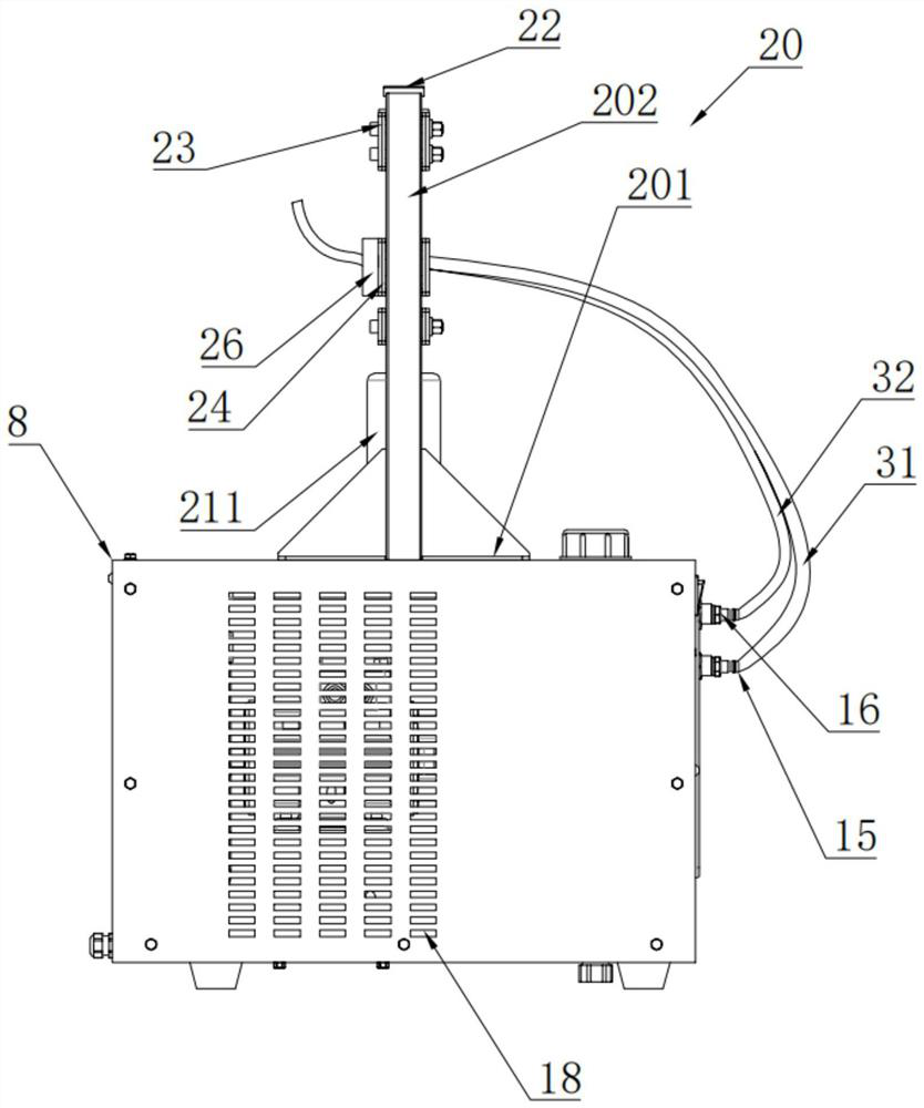
[0031] refer to Figure 1-8 As shown, the automatic locking clamp device of this embodiment is characterized in that it includes

[0032] The clamping device 1 is arranged at the end of the stainless steel belt, and is used to pull the stainless steel belt around the workpiece;

[0033] The limiter 2 is set on the stainless steel belt and is used to limit the supply length of the stainless steel belt and stop the stainless steel belt;

[0034] Spot welding device 3, located next to the workpiece, is used to lock the stainless steel band around the workpiece;

[0035] The driving wheel 4 is arranged on the stainless steel belt and is used to provide power for the stainless steel belt;

[0036] The cutting device 5 is located at the end of the stainless steel strip and is used to pinch off the stainless steel strip. The cutting devic...


PUM


Abstract

The invention discloses an automatic hoop locking device, comprising: a clamping device arranged at the end of a stainless steel strip and used for pulling the stainless steel strip to surround a workpiece; a limiter arranged on the stainless steel strip and used for limiting the supply length of the stainless steel strip and stopping the stainless steel strip; a spot welding device located beside the workpiece and used for locking the stainless steel strip surrounding the workpiece; a movable wheel arranged on the stainless steel strip and used for providing power for the stainless steel strip; a material cutting device located at the end of the stainless steel strip, used for clamping and cutting off the stainless steel strip, and forming an integrated structure with the clamping device; a trimming device used for trimming a welded part; and a cooling device used for reducing the temperature of the welded part. The trimming device and the cooling device are connected with each other; and the trimming device provides power for the cold water device to move up and down. The hoop locking device is automatically installed, so that the production efficiency is improved, and the universal effect of equipment is achieved.

Description

technical field [0001] The invention relates to the technical field of fastening and sealing, in particular to automatic locking clamp equipment. Background technique [0002] There are many models and different styles of the existing transmission shaft assembly, and the assembly is more complicated due to different types and shapes when installing the clamp. When installing the locking clip, staff are required to assist from the side, the work efficiency is low, the labor cost is high, and it does not meet the high-efficiency and low-cost production method. Contents of the invention [0003] Aiming at the deficiencies in the prior art, the object of the present invention is to provide automatic locking clamp equipment to automatically install the locking clamp device, improve production efficiency, and achieve the effect of universal equipment. [0004] In order to achieve the above object, the present invention provides the following technical solutions: automatic locki...

Claims


Application Information

Patent Timeline
Patent Type & Authority Applications(China)
IPC IPC(8): B23P23/00
CPCB23P23/00
Inventor 李德进熊孜向浦江杨波邓凯
Owner ZHEJIANG TELFORD PRECISION DRIVE MFG CO LTD
Learn More