A hook type elevator panel
An elevator panel and hook-type technology, applied in the elevator field, can solve the problems of cumbersome fastening and disassembly of threaded connections, time-consuming and labor-intensive problems
- Summary
- Abstract
- Description
- Claims
- Application Information
AI Technical Summary
Problems solved by technology
Method used
Image

Examples
Embodiment 1
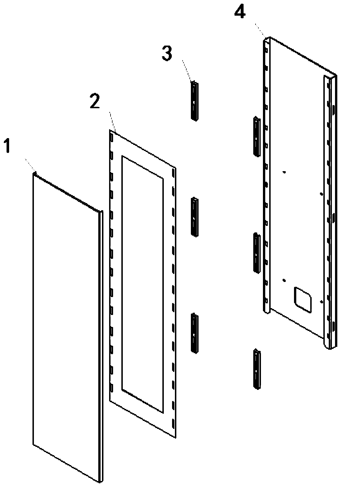
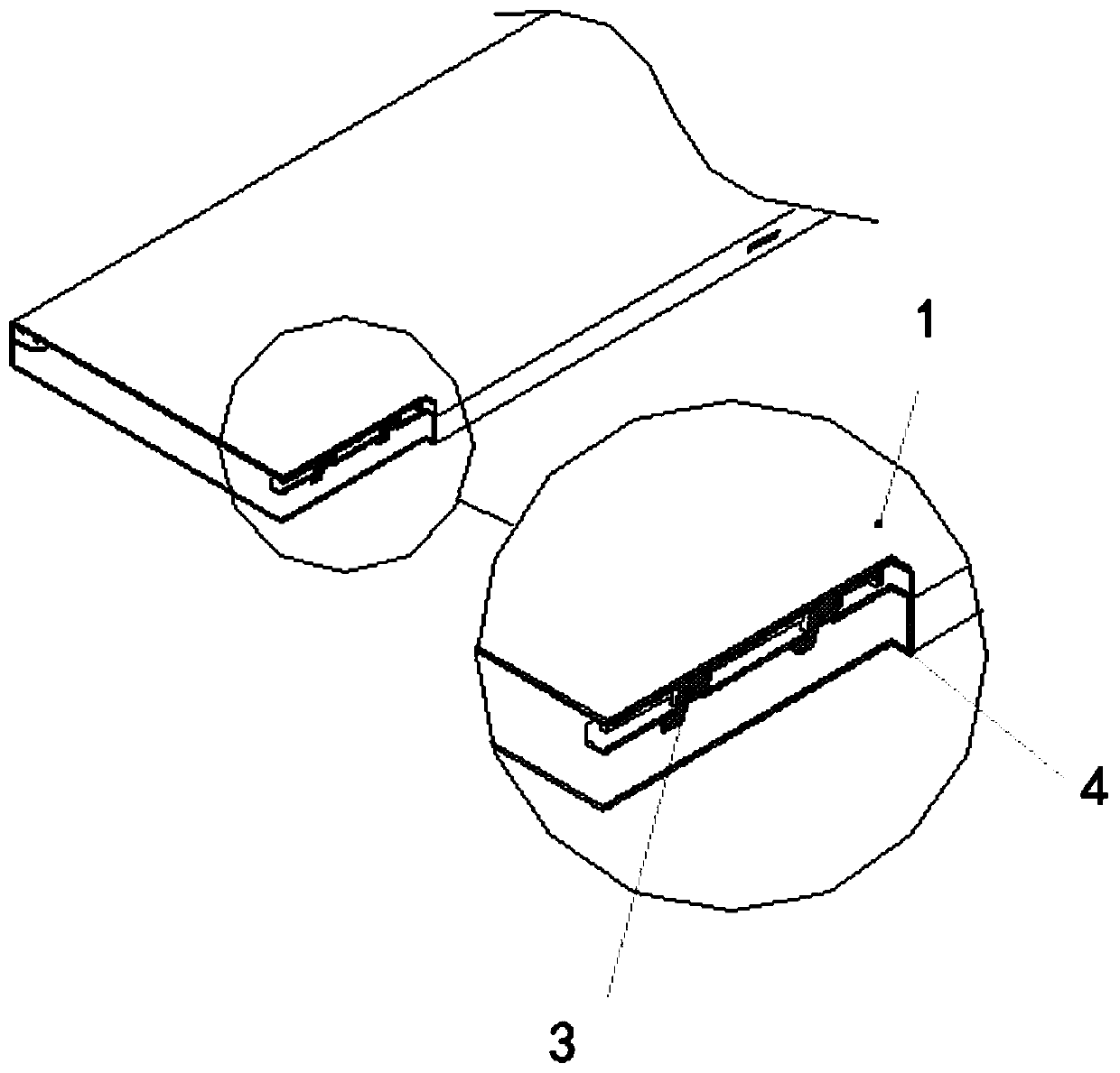
[0028] This embodiment provides a hook type elevator panel, such as figure 1 As shown, the elevator panel includes a panel 1, a liner 2, a plastic hook 3 and a fixed base 4, the liner 2 is glued on the panel 1, and the liner 2 is provided with installation holes, and the installation holes are evenly distributed on the liner 2 sides, one side of the plastic hook 3 is connected to the panel 1 through the installation hole, and the fixed base 4 is installed on the other side of the plastic hook 3 to complete the installation of the elevator panel 1.
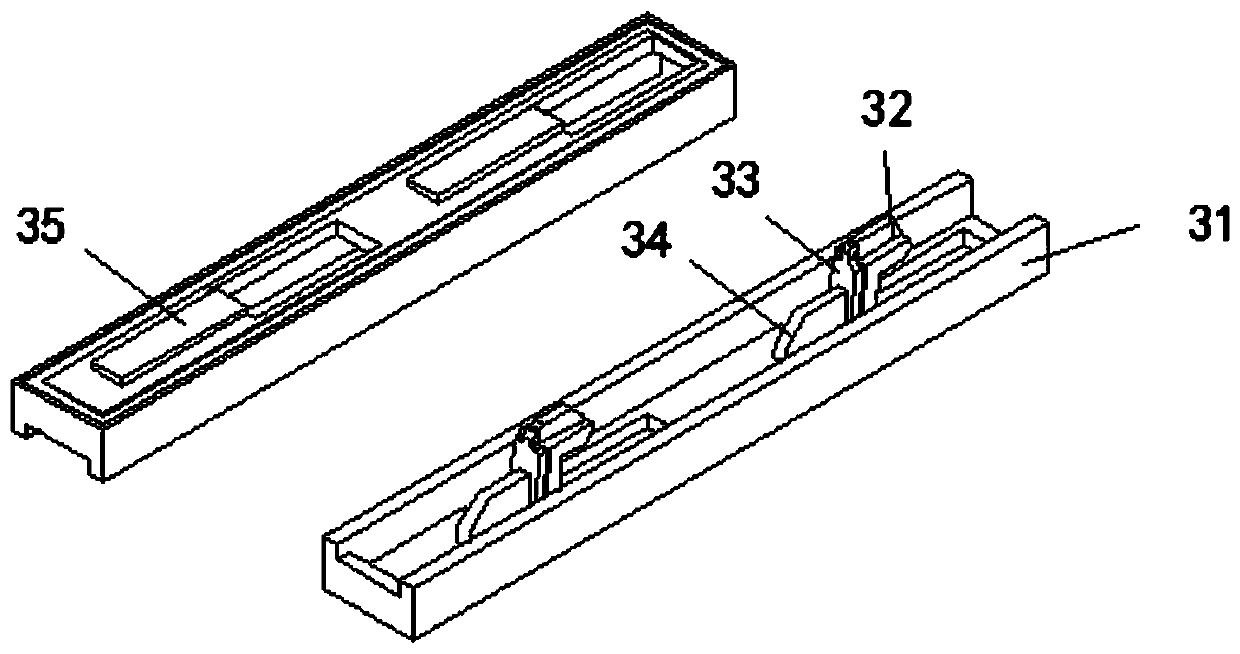
[0029] The plastic hook 3 includes a base plate 31 and an assembly hook, such as figure 2As shown, the cross-section of the substrate 31 is in a concave shape, and the assembly hook is arranged on the concave surface of the substrate 31. On the side opposite to the concave surface of the substrate 31, rectangular bosses 35 are evenly distributed, and the intervals between the rectangular bosses 35 are installed with the liner 2. ...
Embodiment 2
[0033] The difference between this embodiment and the first embodiment is that the installation position of the plastic hook 3 can be adjusted. Adjust the spacing of the assembly hooks on the concave surface of the base plate 31 to meet different installation requirements. The plastic hook 3 includes a base plate 31 , an assembly hook and a fixing piece 36 , the cross section of the base plate 31 is concave, and the assembly hook and the fixing piece 36 are installed inside the concave surface of the base plate 31 . Rectangular bosses 35 are evenly distributed on the opposite side of the concave surface of the substrate 31, the interval between the rectangular bosses 35 is consistent with the spacing of the installation holes of the liner 2, the thickness of the rectangular bosses 35 is the same as the depth of the installation holes, and the plastic hook 3 will The rectangular boss 35 is embedded in the installation hole of the lining plate 2; the opposite side walls of the c...
Embodiment 3
[0036] The difference between this embodiment and the second embodiment is that the assembly hook can not only move up and down along the concave surface of the substrate, but also can be adjusted left and right. Described plastic hook 3 comprises base plate 31, assembly hook, dividing plate 38 and fixing piece 36, and base plate 31 cross-section is concave shape, dividing plate 38, assembly hook and fixing piece 36 are all installed on the concave side of base plate 31, dividing plate 38 Placed between the concave surface of the substrate 31 and the hook of the assembly, a partition is formed between the partition 38 and the concave side of the substrate 31 , and the assembly hook is installed on the partition 38 . The opposite side walls of the concave surface of the substrate 31 are provided with tooth-like protrusions 37, the tooth-like protrusions 37 are equally spaced, the distance between the tooth-like protrusions 37 is equivalent to the thickness of the fixing part 36,...
PUM
 Abstract
Description
Claims
Application Information
 - R&D
- Intellectual Property
- Life Sciences
- Materials
- Tech Scout
- Unparalleled Data Quality
- Higher Quality Content
- 60% Fewer Hallucinations
Browse by: Latest US Patents, China's latest patents, Technical Efficacy Thesaurus, Application Domain, Technology Topic, Popular Technical Reports.
© 2025 PatSnap. All rights reserved.Legal|Privacy policy|Modern Slavery Act Transparency Statement|Sitemap|About US| Contact US: help@patsnap.com