Installation protection structure of liquid crystal screen in liquid crystal television

A technology of LCD TV and protective structure, which is applied to the parts of color TV, parts of TV system, TV, etc. It can solve the problems of damage, buckle structure wear, and shorten the service life of the screen, so as to reduce the number of jitter and jitter range, reduce the probability of damage, and enhance the effect of practical value

Pending Publication Date: 2021-04-09
湖北一杰电子股份有限公司
View PDF0 Cites 0 Cited by
  • Summary
  • Abstract
  • Description
  • Claims
  • Application Information

AI Technical Summary

Problems solved by technology

[0003] Existing liquid crystal screens are fastened directly through the matching screen installation frame after packaging, and the fastening method is mostly a buckle structure and a screw, which results in the need to use a large amount of manpower for installation and disassembly. operation, and when the LCD screen is disassembled and installed many times, it is often easy to control the force poorly, causing wear or damage to the buckle structure in the screen installation frame, reducing the installation effect of the subsequent LCD screen, and the existing LCD screen is in contact with the screen. When the installation frame is installed, it is mostly rigidly connected, which is not conducive to the protection effect of transportation or daily use, because during transportation or daily use, the screen will inevitably be shaken by accidental touches, which increases the probability of damage and damage, and is easy to shorten Lifespan of the screen

Method used


Image

  • Installation protection structure of liquid crystal screen in liquid crystal television
  • Installation protection structure of liquid crystal screen in liquid crystal television
  • Installation protection structure of liquid crystal screen in liquid crystal television

Examples


Embodiment Construction

[0026] The following will clearly and completely describe the technical solutions in the embodiments of the present invention with reference to the accompanying drawings in the embodiments of the present invention. Obviously, the described embodiments are only some, not all, embodiments of the present invention. Based on the embodiments of the present invention, all other embodiments obtained by persons of ordinary skill in the art without making creative efforts belong to the protection scope of the present invention.

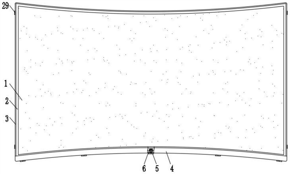
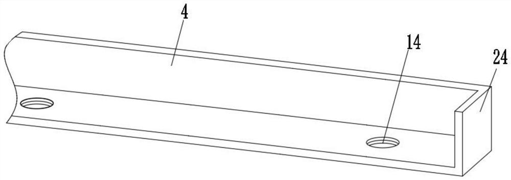
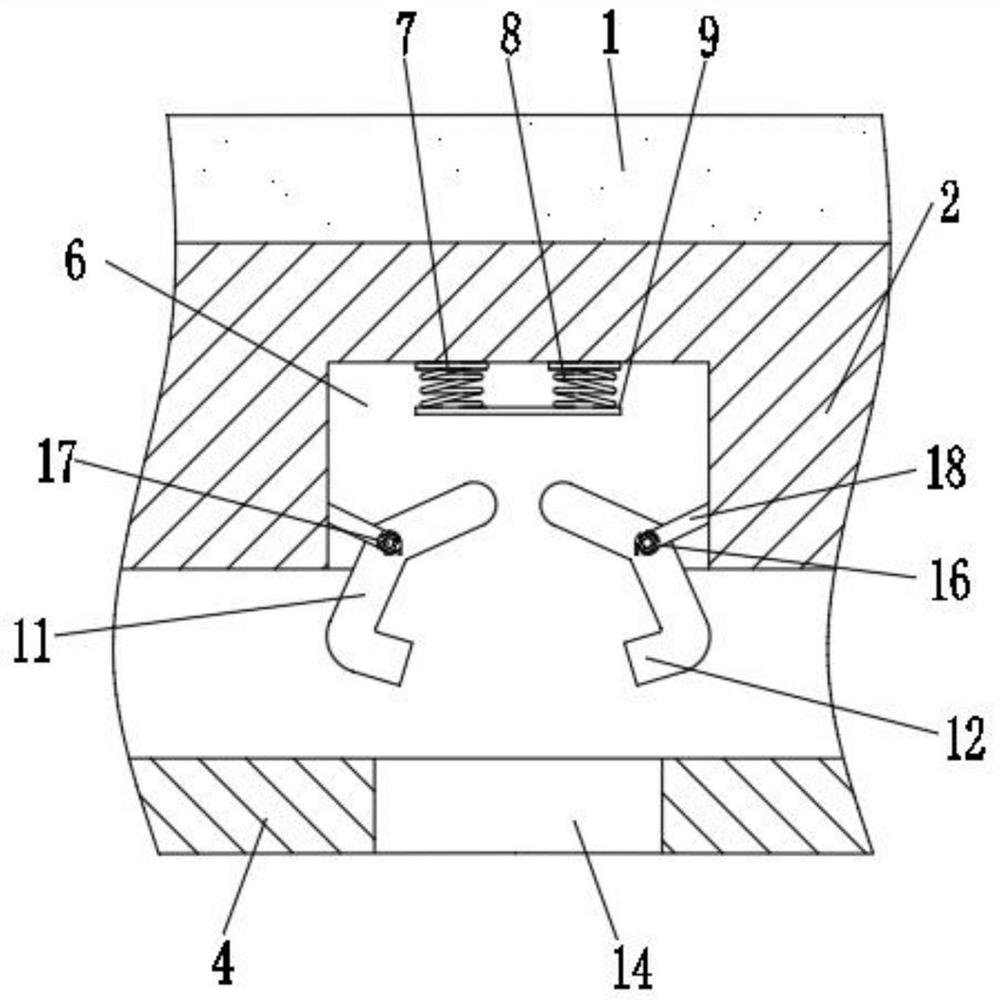
[0027] see Figure 1~6 , in an embodiment of the present invention, an installation and protection structure for a liquid crystal screen in a liquid crystal television, including a screen edge band 2 for encapsulating the four edges of the liquid crystal screen 1, the top edge and two sides of the screen edge band 2 The inner peripheral surfaces corresponding to the installation frame 3 are connected by locking bolts 29, and the bottom edge of the screen edge ...


PUM


Abstract

The invention discloses an installation protection structure of a liquid crystal screen in a liquid crystal display television, and relates to the technical field of liquid crystal screen assembly. The structure comprises screen edge sealing strips used for sealing four edges of the liquid crystal screen, wherein the top edges and two side edges of the screen edge sealing strips are connected with the corresponding inner peripheral surfaces of an installation frame through locking bolts; the bottom edge of the screen edge sealing strip is detachably installed in the bottom supporting plate through a plurality of disassembling and assembling pieces, and each disassembling and assembling piece comprises a connecting piece capable of being disassembled relative to the bottom supporting plate and a trigger positioning piece arranged on the lower edge of the screen edge sealing strip and connected with the connecting piece in a matched mode. The disassembly and assembly part can achieve the purpose of connecting and sealing the bottom supporting plate to the bottom edge of the screen edge sealing strip and can be matched with the elastic part to achieve the protection effect on the bottom of the screen edge sealing strip, and meanwhile, the disassembly and assembly part and the lower side of the screen edge sealing strip can further achieve the shock absorption and buffering effect on the screen edge sealing strip; the double effects of installation and protection are achieved, and the obvious actual use effect is achieved.

Description

technical field [0001] The invention relates to the technical field of liquid crystal screen assembly, in particular to an installation protection structure for a liquid crystal screen in a liquid crystal television. Background technique [0002] Liquid crystal display, referred to as LCD, adopts a substance between solid and liquid, organic compounds with regular molecular arrangement, heated to a transparent liquid state, and crystal particles to appear in a turbid solid state after cooling; LCD screen, Including LCD monitors and LED monitors, the current stimulates liquid crystal molecules to generate points, lines, and surfaces to form a picture with the back light tube. Compared with traditional cathode ray tube (CRT) monitors, it has a relatively large volume, soft images, no flickering images, and reduces eye fatigue. [0003] Existing liquid crystal screens are fastened directly through the matching screen installation frame after packaging, and the fastening method...

Claims


Application Information

Patent Timeline
Patent Type & Authority Applications(China)
IPC IPC(8): H04N5/64F16F15/02F16F15/067
CPCF16F15/02F16F15/067H04N5/64
Inventor 黄大勇
Owner 湖北一杰电子股份有限公司
Why Eureka
Try Eureka