
Conventional direct-current valve area fault positioning method

A fault location, conventional DC technology, applied in the field of power systems, can solve problems such as economic loss, trouble spot troubleshooting that takes a lot of time, analysis and rigidity, and achieve the effect of reducing misjudgment

Pending Publication Date: 2021-04-09
CSG EHV POWER TRANSMISSION +1
View PDF0 Cites 0 Cited by
  • Summary
  • Abstract
  • Description
  • Claims
  • Application Information

AI Technical Summary

Problems solved by technology

If the possible area where the fault occurs cannot be narrowed down based on the waveform and the message, it may take a lot of time to troubleshoot the fault point on site, prolong the DC outage time, and bring mode restrictions and economic losses to the power system dispatching operation
In recent years, the fault diagnosis and location of DC systems have been widely studied. Some literatures have carried out in-depth analysis of the protection action characteristics of conventional valve zone faults, but most of the analysis is limited to the existing valve short-circuit protection criteria, and the analysis process is complicated. Accuracy is also poor
Some literatures construct the current integral criterion to judge the fault location of the valve area, but the criterion needs to use the current of the conventional DC bridge arm, and the thyristor converter valve bridge arm is generally not equipped with a current transformer, which brings difficulties to engineering applications

Method used


Image

  • Conventional direct-current valve area fault positioning method
  • Conventional direct-current valve area fault positioning method
  • Conventional direct-current valve area fault positioning method

Examples


Embodiment Construction

[0046] In order to make the above objects, features and advantages of the present invention more comprehensible, the technical solutions of the present invention will be described in detail below in conjunction with the accompanying drawings and specific embodiments. It should be pointed out that the described embodiments are only a part of the embodiments of the present invention, rather than all embodiments. Based on the embodiments of the present invention, all those skilled in the art can obtain without creative work. Other embodiments all belong to the protection scope of the present invention.

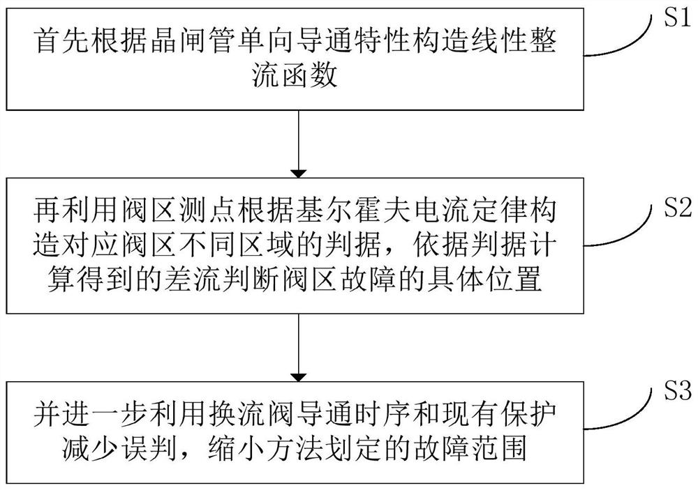
[0047] Such as figure 1 As shown, the present invention provides a method for locating faults in conventional DC valve areas, including the following steps:

[0048] S1. Modeling of conduction characteristics of thyristor converter valve

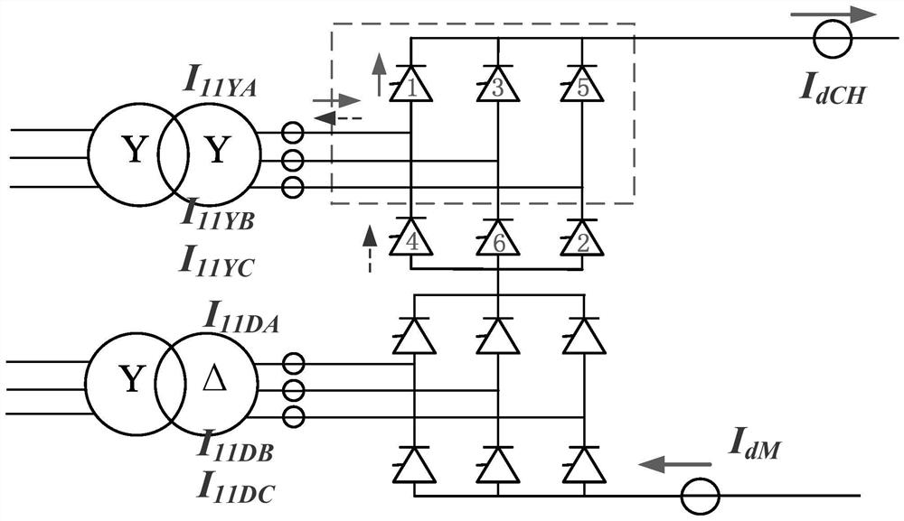
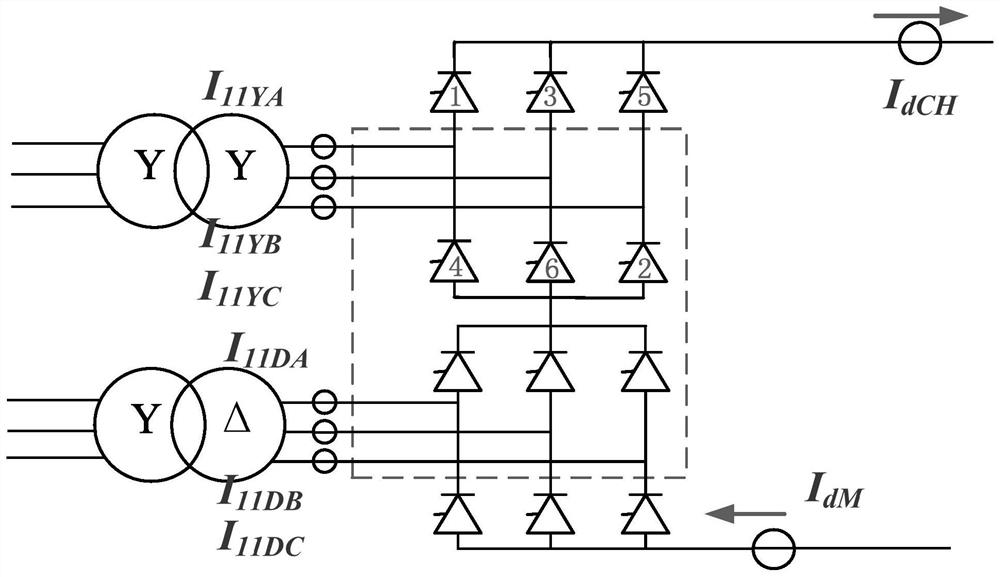
[0049] The schematic diagram of the common UHV DC high-valve twelve-pulse converter and its converter transformer is as follows: figure 2 ...


PUM


Abstract

The invention discloses a conventional direct-current valve area fault positioning method. The method comprises the following steps: firstly, constructing a linear rectification function according to the one-way conduction characteristic of a thyristor; constructing criteria corresponding to different areas of the valve area according to the Kirchhoff's current law by utilizing the valve area measuring points, and judging the specific position of the valve area fault according to the differential flow calculated according to the criteria; and reducing misjudgment by further utilizing the conduction time sequence of the converter valve and the existing protection, and reducing the fault range defined by the method. The partitions corresponding to the criterion are accurate to the phase by using the conduction time sequence of the converter valve, and the adverse effect of commutation failure on criterion use is eliminated by combining the existing direct current protection. In the analysis of an actual fault event, the valve area fault positioning algorithm provided by the invention gives a valve area fault positioning result which is accurate to the phase. Analysis and simulation tests show that the method has practical value.

Description

technical field [0001] The invention relates to the technical field of power systems, in particular to a method for locating a fault in a conventional DC valve area. Background technique [0002] The long-distance and large-capacity direct current transmission project is an important power infrastructure and an important cornerstone of economic development. The safe and stable operation of DC transmission projects is an important part of the reliability of power systems. In conventional DC projects, the DC control and protection system itself is equipped with redundant layered and partitioned protection, which is used to isolate and clear faults as soon as possible when a fault occurs, protect the primary equipment of the DC transmission project, and ensure DC power transmission as much as possible. [0003] However, in actual operation, it is found that some faults in the valve area often cause protection actions in multiple valve areas and polar areas, which makes it diff...

Claims


Application Information

Patent Timeline
Patent Type & Authority Applications(China)
IPC IPC(8): G01R31/08
CPCG01R31/088
Inventor 罗炜龙启陈德扬廖毅蒋峰伟
Owner CSG EHV POWER TRANSMISSION
Learn More