Vacuum particle counter

A counter and particle technology, which is applied in scientific instruments, individual particle analysis, particle and sedimentation analysis, etc., can solve the problems of no particle counter, no uniform directionality of particles, and difficulty in particle monitoring, so as to increase the effective measurement area. , Increase the probability of particle detection, and expand the effect of collecting solid angle

Active Publication Date: 2021-04-09
SHANGHAI ADVANCED RES INST CHINESE ACADEMY OF SCI
View PDF17 Cites 0 Cited by
  • Summary
  • Abstract
  • Description
  • Claims
  • Application Information

AI Technical Summary

Problems solved by technology

[0003] However, in a vacuum environment, especially in a high vacuum, gas molecules move in the form of a molecular flow, and the direction of their movement is random, resulting in the movement of particles in the environment without uniform directionality, so it is difficult to monitor particles, and There are currently no particle counters designed for use in vacuum
The problem with the detection unit in the currently used air-borne particle counter is that the measurement area is small, generally less than 10 5 On the order of cubic microns, the probability of detecting randomly moving particles in a high vacuum environment is very small, which cannot be used for particle monitoring in a vacuum environment

Method used


Image

  • Vacuum particle counter
  • Vacuum particle counter
  • Vacuum particle counter

Examples


Embodiment 1

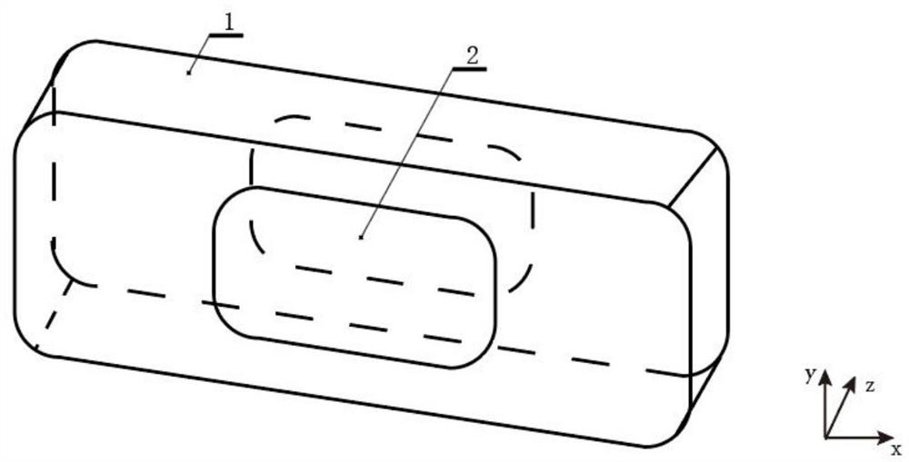
[0036] Such as figure 1 As shown, the embodiment of the present invention provides a vacuum particle counter, including a housing 1, which has a measurement hole 2 passing through the housing 1 along the z direction. The housing 1 can be an aluminum cuboid with a hollow interior, and is blackened to reduce Scattering of light on the inner and outer surfaces of the housing 1, in this embodiment, the x-direction length can be 7 to 12 centimeters, the y-direction width can be 2 to 3.5 centimeters, and the z-direction thickness can be 1.2 to 2 centimeters; the measuring hole 2 can be Set in the middle of the housing 1, it is a long hole, the x-direction length can be set to 3 to 5 cm, and the y-direction width can be set to 1.5 to 3 cm, which can ensure that the particles in the vacuum system to be detected have a sufficient size probability to move into the measurement hole 2, thereby increasing the probability of detecting particles.

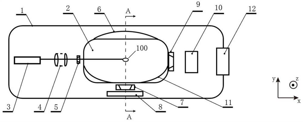
[0037] Such as figure 2 As shown, the in...

Embodiment 2

[0054] This embodiment provides a vacuum particle counter whose structure is basically the same as the vacuum particle counter in the first embodiment, except that the structure of the light detection part in the first embodiment is improved. Such as Figure 12 As shown, the vacuum particle counter of this embodiment includes a housing 1', which has a measuring hole 2' passing through the housing 1' along the z direction. The width of the housing 1' can be set to 3.5 cm and the thickness is 3.5 cm.

[0055]The inside of the housing 1' is sequentially fixed with a light incident part, a light exit part and a light detection part along the x direction, wherein the light incident part is located on the side of the measurement hole 2' in the x direction, and includes lasers 3' arranged in sequence along the x direction, the incident The structure of the optical element group 4 ′ and the entrance diaphragm 5 ′ is the same as that in the first embodiment, and will not be repeated he...


PUM


Abstract

The invention relates to a vacuum micro-particle counter which comprises a shell; the shell is provided with a measuring hole penetrating through the shell in the z direction, and the interior of the shell is fixedly provided with light incident parts, light detection parts and a light emitting part; the light incident parts are used for emitting laser and forming a flat-topped light beam with the cross section light intensity evenly distributed, are located on one side of a measuring hole, and each comprise a laser device, an incident optical element set and an incident diaphragm which are sequentially arranged in the x direction; incident optical element groups each comprise a focusing lens, a light homogenizing rod and a lens group which are sequentially arranged along the x direction; the light detection parts collect scattered light formed by scattering the flat-topped light beam by the micro-particles and detect the number of the micro-particles on the basis of the collected scattered light; and the light emitting part and the light incident parts are oppositely positioned on the other side of the measuring hole, and the light emitting part is used for absorbing the part, which is not scattered by the micro-particles, in the laser emitted by the light incident parts. According to the vacuum micro-particle counter, the special incident light path comprising the light homogenizing rod is adopted, so that incident laser forms a flat-topped light beam with uniformly distributed cross section light intensity, and an effective measurement area can be increased.

Description

technical field [0001] The invention relates to the field of dust-free processing and manufacturing and vacuum technology, and more particularly relates to a vacuum particle counter. Background technique [0002] Dust-free manufacturing has strict cleanliness requirements for the processing environment. For example, cleanliness level 10 requires that the number of particles larger than 0.1 microns in the environment is less than 10,000 per cubic meter. In some applications, such as high-energy particle accelerators , Chip manufacturing in the semiconductor industry, and thin-film panel production and assembly in the photovoltaic and display industries also involve a vacuum environment, so there are also dust-free requirements for the entire vacuum process involved in manufacturing and processing. Air-borne particle counters are generally used to monitor the number of particles of different sizes in the atmospheric environment. The principle is to collect the air in the envir...

Claims


Application Information

Patent Timeline
Patent Type & Authority Applications(China)
IPC IPC(8): G01N15/10
CPCG01N15/10G01N2015/105G01N2015/1062
Inventor 赵烨梁胡晓
Owner SHANGHAI ADVANCED RES INST CHINESE ACADEMY OF SCI
Why Eureka
Try Eureka