Hinge of inward tilt-turn window and inward tilt-turn window

A technology of hinges and inverted windows, applied in the field of doors and windows, can solve problems such as insufficient support strength, and achieve the effects of small torque, good bearing performance, and high support strength

Pending Publication Date: 2021-04-09
佛山市顺德区科能实业有限公司
View PDF0 Cites 0 Cited by
  • Summary
  • Abstract
  • Description
  • Claims
  • Application Information

AI Technical Summary

Problems solved by technology

In the existing inverted windows that open inward, when the inner window is opened outward, it is supported by the hinge piece, and when the inner window is opened inwardly, the inner window can slide and rotate inward relative to the hinge piece. On the hinge piece, the support strength is not enough

Method used


Image

  • Hinge of inward tilt-turn window and inward tilt-turn window
  • Hinge of inward tilt-turn window and inward tilt-turn window
  • Hinge of inward tilt-turn window and inward tilt-turn window

Examples


Embodiment 1

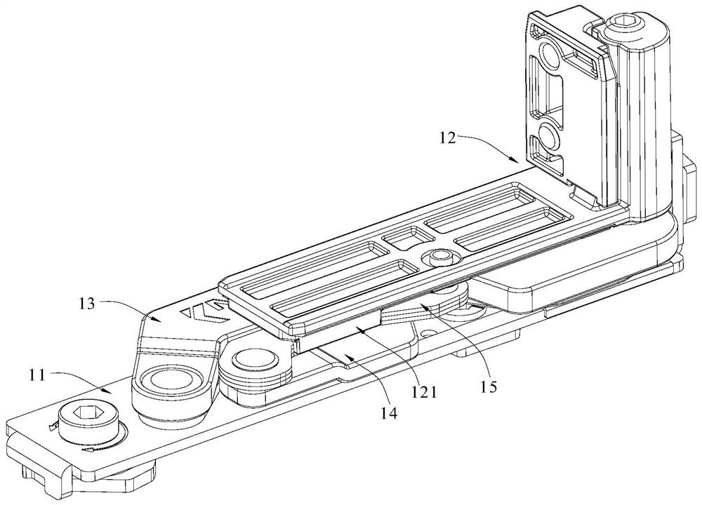
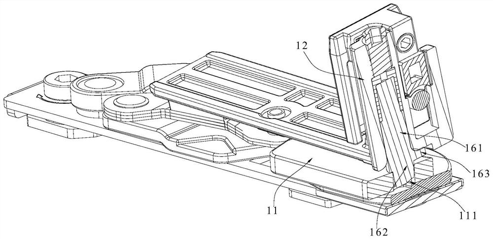
[0039] Such as figure 1 The hinge 10 shown in -8 includes the first hinge seat 11, the second hinge seat 12, the first hinge piece 13, the second hinge piece 14, the elastic member 15 and the inner turning piece, specifically the first hinge One end of the piece 13 is hinged on the first hinge seat 11 and forms a first hinge end, and the other end of the first hinge piece 13 is hinged on the second hinge seat 12 .

[0040] In addition, one end of the second hinged piece 14 is hinged on the first hinged seat 11 and is formed as a second hinged end, and the other end of the second hinged piece 14 is hinged with one end of the elastic member 15; The second hinged seat 12 is formed as a third hinged end. Moreover, the first hinged piece 13 and the second hinged piece 14 are cross-hinged, and the first hinged end and the second hinged end are arranged at intervals. In addition, the second hinged seat 12 can also rotate inward with the third hinged end as a fulcrum.

[0041] One e...

Embodiment 2

[0057] Such as figure 1 The inward-opening window shown in -11 includes an outer frame 20, an inner frame 30, and the above-mentioned hinge 10, and the hinge 10 includes a first hinge seat 11, a second hinge seat 12, a first hinge piece 13, and a second hinge piece 14 , the elastic part 15 and the inner inverted part, specifically, one end of the first hinged piece 13 is hinged on the first hinged seat 11 and is formed as a first hinged end, while the other end of the first hinged piece 13 is hinged on the second hinged seat 12 .

[0058] In addition, one end of the second hinged piece 14 is hinged on the first hinged seat 11 and is formed as a second hinged end, and the other end of the second hinged piece 14 is hinged with one end of the elastic member 15; The second hinged seat 12 is formed as a third hinged end. Moreover, the first hinged piece 13 and the second hinged piece 14 are cross-hinged, and the first hinged end and the second hinged end are arranged at intervals...


PUM


Abstract

The invention discloses a hinge of an inward tilt-turn window and the inward tilt-turn window. The hinge comprises a first hinge seat, a second hinge seat, a first hinge piece, a second hinge piece, an elastic component and an inward tilt-turn piece, wherein the first hinge piece and the second hinge piece are hinged in a crossed manner; the other end of the second hinge piece is hinged to one end of the elastic component; the other end of the elastic component is hinged to the second hinge seat and forms a third hinge end; the first hinge end and the second hinge end are arranged at an interval; one end of the inward tilt-turn piece forms a connecting end, and the other end of the inward tilt-turn piece forms a swing end; an abutting piece is arranged on the outer surface of the inward tilt-turn piece in a protruding manner; the connecting end is connected into the second hinge seat; a swing groove is formed in the first hinge seat, and the swing end is connected into the swing groove in a penetrating manner and can swing around a vertical shaft; and the abutting piece is used for abutting against the bottom end surface of the second hinge seat. The inward tilt-turn window comprises an outer frame, an inner frame and the hinge. An inward tilt-turn acting point can be attached to a window frame, and the strength is increased.

Description

technical field [0001] The invention relates to the technical field of doors and windows, in particular to a hinge for a tilt-in window and a tilt-in window. Background technique [0002] At present, by turning the handle of the window to turn the window, the linkage hardware mechanism inside the window can be driven, so that the window can be locked (the handle is vertically downward), opened horizontally (the handle is horizontal), and inverted (the handle is vertically upward). ) windows in three different positions. In the existing inverted windows that open inward, when the inner window is opened outward, it is supported by the hinge piece, and when the inner window is opened inwardly, the inner window can slide and rotate inward relative to the hinge piece. On the hinge piece, the support strength is not enough. Contents of the invention [0003] In order to overcome the deficiencies of the prior art, one of the objectives of the present invention is to provide a h...

Claims


Application Information

Patent Timeline
IPC IPC(8): E05D15/52E05D15/526E05D15/54E06B3/50
CPCE05D15/52E05D15/5214E05D15/526E05D15/54E06B3/50
Inventor 袁发贤范水旺
Owner 佛山市顺德区科能实业有限公司
Why Eureka
Try Eureka