Uniform splitting equipment for leather processing
A leather and uniform technology is applied in the field of uniform splitting equipment for leather processing, which can solve the problems of troublesome and laborious operation.
- Summary
- Abstract
- Description
- Claims
- Application Information
AI Technical Summary
Problems solved by technology
Method used
Image
Examples
Embodiment 1
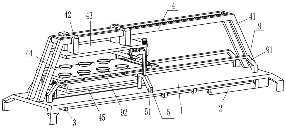
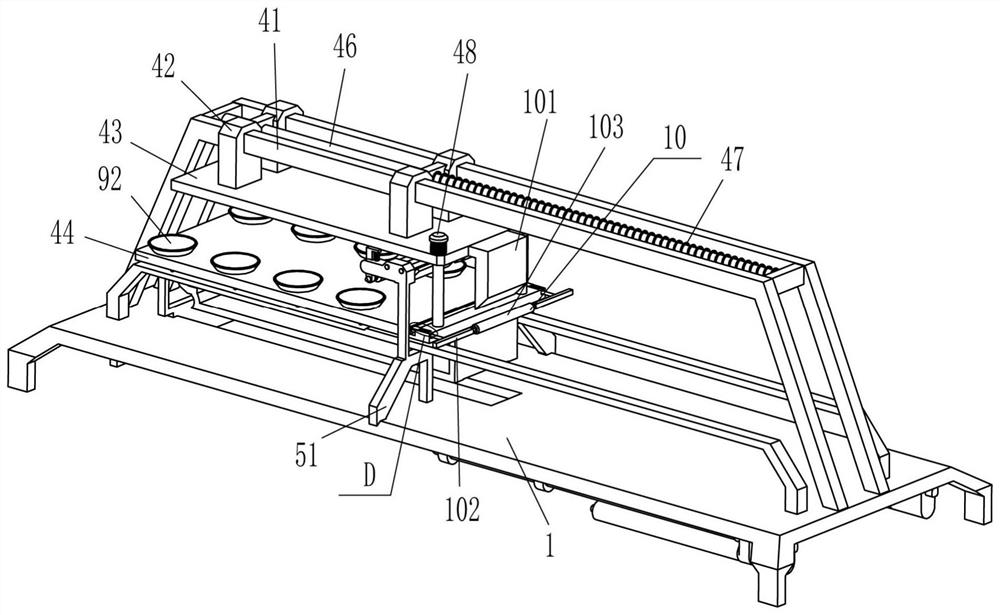
[0027] A kind of uniform splitting equipment for leather processing, such as Figure 1-Figure 4 As shown, it includes a base 1, an electric push rod 2, a sliding frame 3, a placement mechanism 4 and a scraping mechanism 5. The sliding frame 3 is connected to the left side of the base 1 in a sliding manner, and the bottom right side of the base 1 is symmetrically fixed to the front and rear. Electric push rod 2, the end of the telescopic rod of electric push rod 2 is fixedly connected with the lower part of the right side of the sliding frame 3, the top of the base 1 is provided with a placement mechanism 4, the placement mechanism 4 cooperates with the sliding frame 3, and the left side of the top of the base 1 is provided with The scraping mechanism 5 is in contact with the placement mechanism 4 .
[0028] Placement mechanism 4 includes mounting frame 41, n-type slide block 42, wave groove plate 43, placement plate 44, contact plate 45, guide rod 46, first spring 47, guide ro...
Embodiment 2
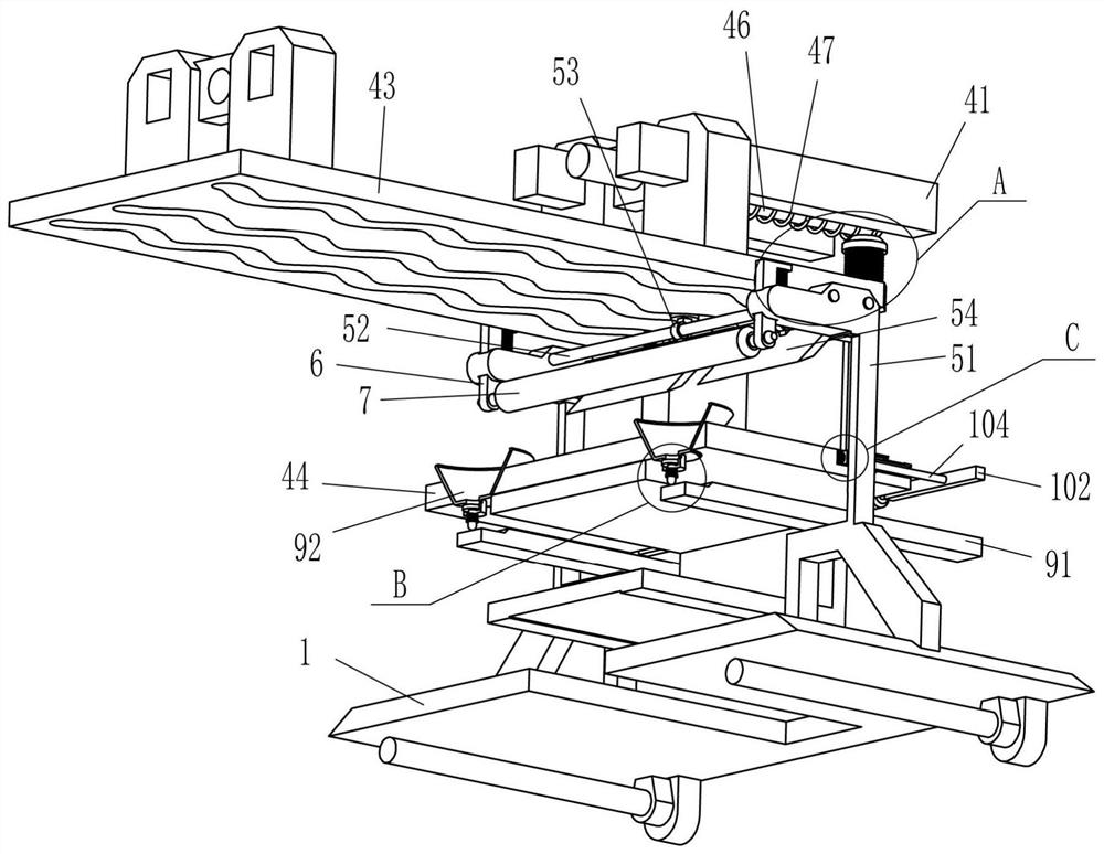
[0034] On the basis of Example 1, such as figure 1 , image 3 , Figure 4 with Figure 5 As shown, it also includes an L-shaped block 6, a pressure roller 7 and a third spring 8, the upper left side of the support frame 51 is slidably connected with an L-shaped block 6, and the inner top of the L-shaped block 6 and the outer top of the support frame 51 A third spring 8 is connected between them, and a pressure roller 7 is connected in rotation between the lower parts of the L-shaped blocks 6 on the front and rear sides.
[0035] Also include suction mechanism 9, suction mechanism 9 includes n-type plate 91, suction cup 92, piston rod 93 and the 4th spring 95, and the fixed penetration of both front and back of placing plate 44 is connected with suction cup 92 at even intervals, each side The number of suction cups 92 is four, and the lower part of the suction cups 92 is evenly spaced circumferentially with exhaust holes 94. The center of the bottom of the suction cups 92 is...
Embodiment 3
[0039] On the basis of embodiment 1 and embodiment 2, such as figure 2 , image 3 , Image 6 with Figure 7 As shown, a clamping mechanism 10 is also included, and the clamping mechanism 10 includes an L-shaped inclined block 101, a fixed rod 102, a roller 103, a movable rod 104, a clip block 105 and a fifth spring 106, and the right side of the wave groove plate 43 The middle part is fixedly connected with an L-shaped inclined block 101, and the front and rear symmetrical sliding type of the placement plate 44 is provided with a movable rod 104, and the right end of the movable rod 104 is fixedly connected with a fixed rod 102, and the inner ends of the fixed rods 102 on the front and rear sides are rotated. The roller 103 is connected with the roller 103, and the roller 103 cooperates with the L-shaped inclined block 101. A clamping block 105 is fixedly connected between the left ends of the movable rods 104 on the front and rear sides. Fifth springs 106 are evenly space...
PUM
 Abstract
Description
Claims
Application Information
 - R&D
- Intellectual Property
- Life Sciences
- Materials
- Tech Scout
- Unparalleled Data Quality
- Higher Quality Content
- 60% Fewer Hallucinations
Browse by: Latest US Patents, China's latest patents, Technical Efficacy Thesaurus, Application Domain, Technology Topic, Popular Technical Reports.
© 2025 PatSnap. All rights reserved.Legal|Privacy policy|Modern Slavery Act Transparency Statement|Sitemap|About US| Contact US: help@patsnap.com


