Cow hair removing device used for leather processing
A cow hair and leather technology, which is applied in raw hide/leather/fur manufacturing equipment, leather manufacturing, small raw hide/big raw hide/leather/fur treatment, etc. It can solve problems such as laborious and difficult to scrape off the cow hair
- Summary
- Abstract
- Description
- Claims
- Application Information
AI Technical Summary
Problems solved by technology
Method used
Image
Examples
Embodiment 1
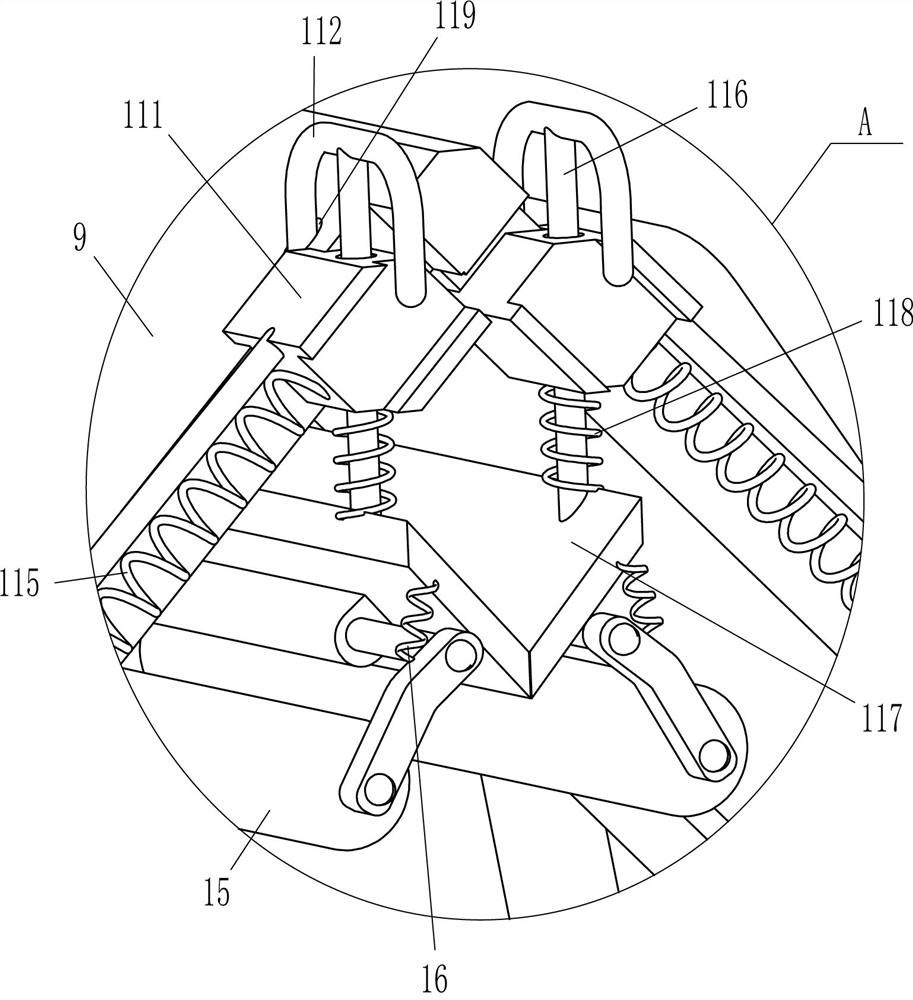
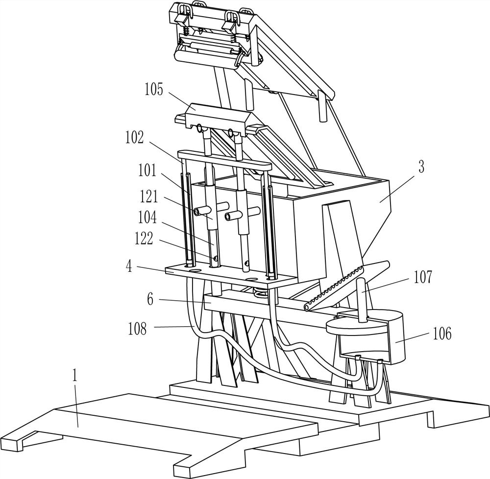
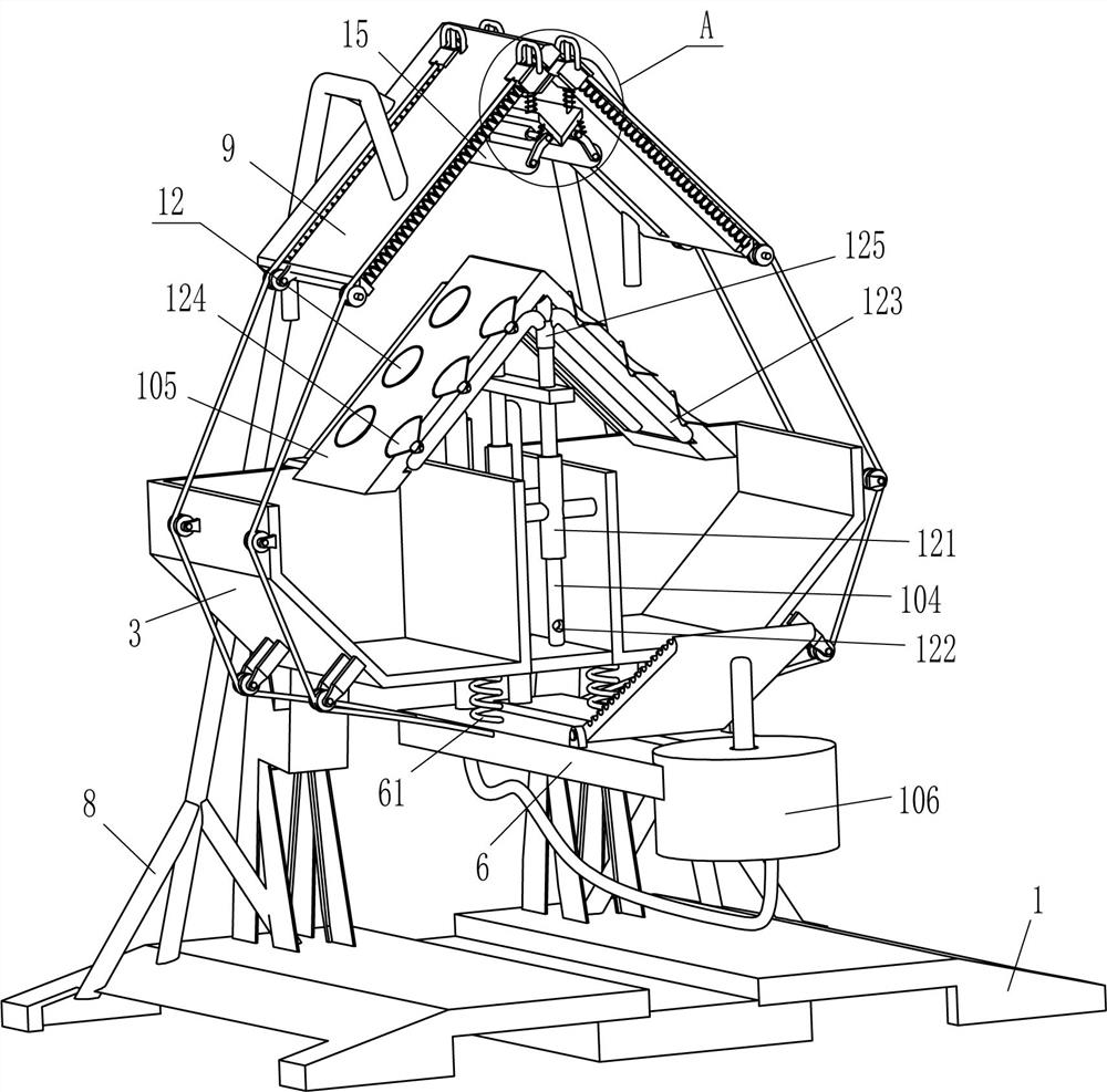
[0023] A kind of cow hair removal device for leather processing, such as Figure 1-Figure 4 As shown, it includes a base 1, a support plate 2, a collection frame 3, a mounting plate 4, a guide rod 5, a movable plate 6, an elastic member 61, a pedal 7, a bracket 8, an L-shaped plate 9, a placement mechanism 10 and a scraping mechanism 11. Support plates 2 are fixed symmetrically on the front and rear sides of the top of the base 1, and the collection frame 3 is fixed between the upper inner surfaces of the two left support plates 2 and the upper inner surfaces of the two right support plates 2 A mounting plate 4 is fixedly connected between the lower part of the outer right side of the left collecting frame 3 and the lower part of the outer left side of the right collecting frame 3, and the front and rear parts of the mounting plate 4 are all symmetrically slidable and connected with guide rods 5 A movable plate 6 is fixedly connected between the bottom ends of the two guide ro...
Embodiment 2
[0030] On the basis of Example 1, such as figure 2 As shown, it also includes a fixing mechanism 12, the fixing mechanism 12 includes a fixing sleeve 121, an air outlet pipe 123, a suction cup 124 and a sleeve pipe 125, and the outer right side of the left collection frame 3 and the outer left side of the right collection frame 3 A fixed sleeve 121 is fixed symmetrically between the upper parts, and the hollow rod 104 slides through the fixed sleeve 121 to fit with it. The upper part of the hollow rod 104 is fixed with a sleeve 125, which communicates with the hollow rod 104, and the L-shaped placement plate Both sides of the left and right sides in 105 are fixedly connected with air outlet pipe 123 symmetrically front and back, the inner end of air outlet pipe 123 is fixedly connected and communicated with sleeve pipe 125, and the left and right sides of the L-shaped placing plate 105 are all evenly spaced with suction cups 124 fixedly connected therein. The end is connected...
Embodiment 3
[0033] On the basis of embodiment 1 and embodiment 2, such as figure 1 , figure 2 and Figure 4 As shown, it also includes a rubber rod 13 and an L-shaped contact plate 14. The L-shaped contact plate 14 is fixedly connected to the front and rear sides of the L-shaped placement plate 105. Rod 13, in the middle of the top of L-shaped plate 9, also is fixedly connected with rubber rod 13 symmetrically front and back, and rubber rod 13 cooperates with L-shaped contact plate 14.
[0034] It also includes a pressure roller 15 and a third spring 16. The middle part of the outer surface of the scraper 117 is rotatably connected with the pressure roller 15. The third spring 16 is connected between the front and rear sides of the outer side of the pressure roller 15 and the front and rear sides of the scraper 117.
[0035] When the L-shaped placement plate 105 moved upwards, the L-shaped placement plate 105 also drove the L-shaped contact plate 14 to move upwards, and the L-shaped co...
PUM
 Abstract
Description
Claims
Application Information
 - R&D
- Intellectual Property
- Life Sciences
- Materials
- Tech Scout
- Unparalleled Data Quality
- Higher Quality Content
- 60% Fewer Hallucinations
Browse by: Latest US Patents, China's latest patents, Technical Efficacy Thesaurus, Application Domain, Technology Topic, Popular Technical Reports.
© 2025 PatSnap. All rights reserved.Legal|Privacy policy|Modern Slavery Act Transparency Statement|Sitemap|About US| Contact US: help@patsnap.com


