


Quick Research
Generate reliable direction feasibility study reports for your R&D in just a few steps.

Technical Q&A
Discover and master advanced knowledge NOW. Basics, ideas, possibilities, all at once.

Find Solutions
As an expert in R&D theories, this can generate solutions to your technical problems instantly.

Evaluate Feasibility
Analyze your overall solution with one click, know your potential R&D risks in advance.

Monitor Landscape
Get weekly tech updates, stay abreast of the latest tech innovations and key insights.
In-ear earphone rubber sleeve burr scraping equipment
A rubber cover and in-ear technology, which is applied in the field of scraping equipment for the rubber cover of in-ear earphones, can solve the problems of scraping tools, damage, low work efficiency, etc., and achieve the effect of avoiding damage
- Summary
- Abstract
- Description
- Claims
- Application Information
AI Technical Summary
Problems solved by technology
Method used
Image

Examples
Embodiment 1
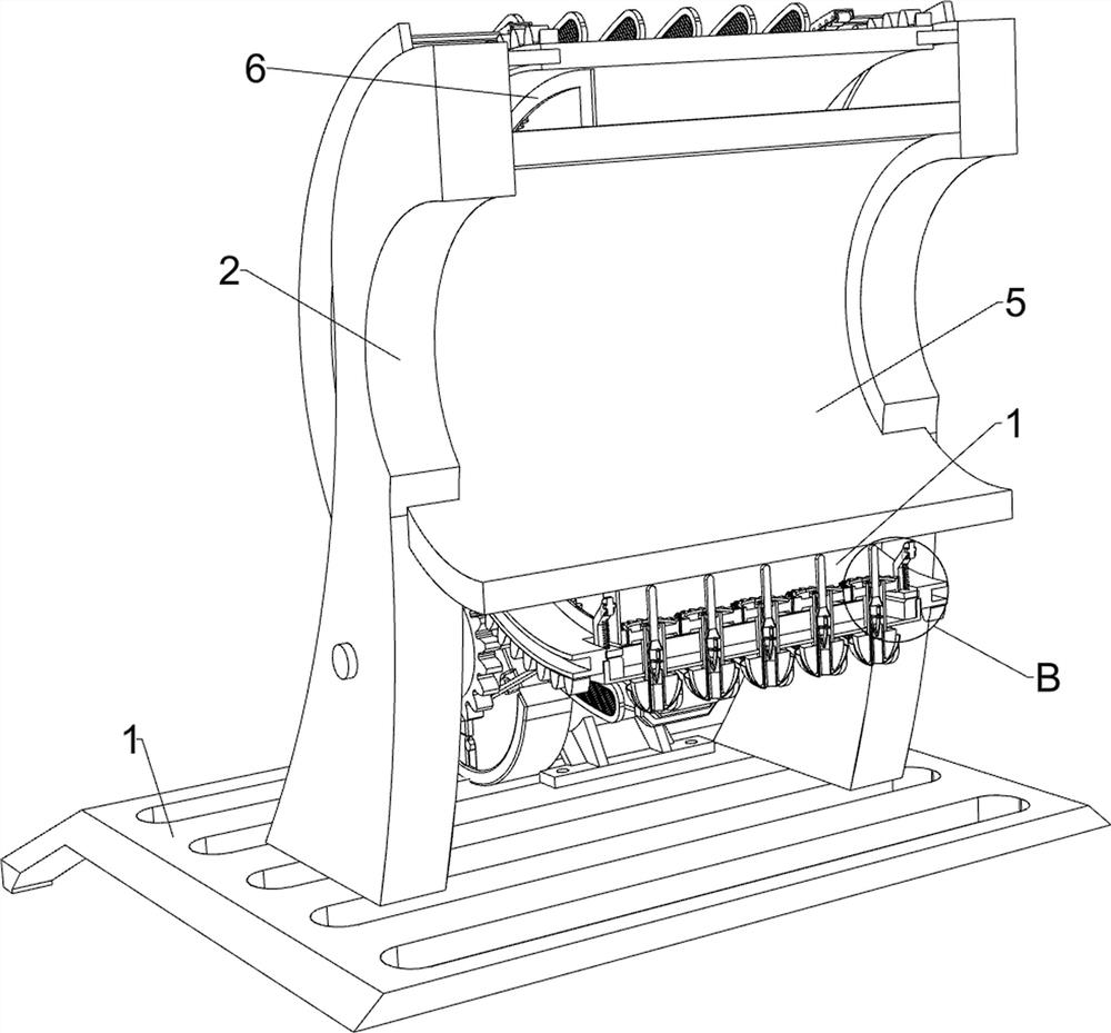
[0025] A kind of in-ear earphone rubber sleeve burr scraping equipment, such as Figure 1-Figure 4 As shown, it includes a base 1, a support plate 2, a u-shaped plate 3, an arc-shaped friction plate 4, an annular cylinder 5, a toothed annular plate 6, a rotating mechanism 7, and a placement mechanism 8. A support plate 2 is fixedly connected, and an annular cylinder 5 is fixedly connected between the upper inner surface of the support plates 2 on the front and rear sides, and a toothed annular plate 6 is affixed to the outer front of the annular cylinder 5 in the circumferential direction. The two support plates 2 and the base 1 A rotating mechanism 7 is provided between the tops, and a placing mechanism 8 is arranged on the rotating mechanism 7. The placing mechanism 8 cooperates with the toothed annular plate 6, and a U-shaped plate 3 is fixedly connected between the upper left side of the support plate 2 on the front and rear sides. Evenly spaced sliding sleeves on the u-sh...
Embodiment 2
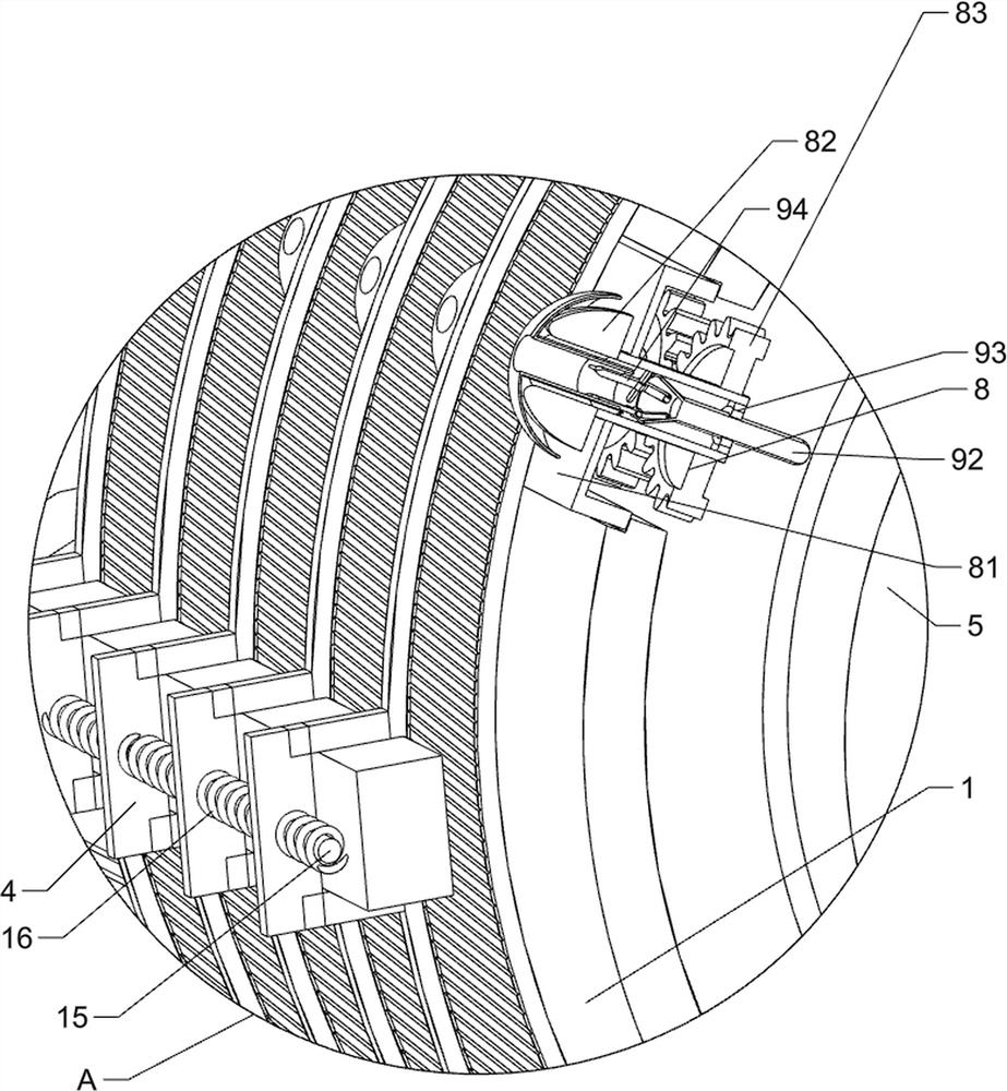
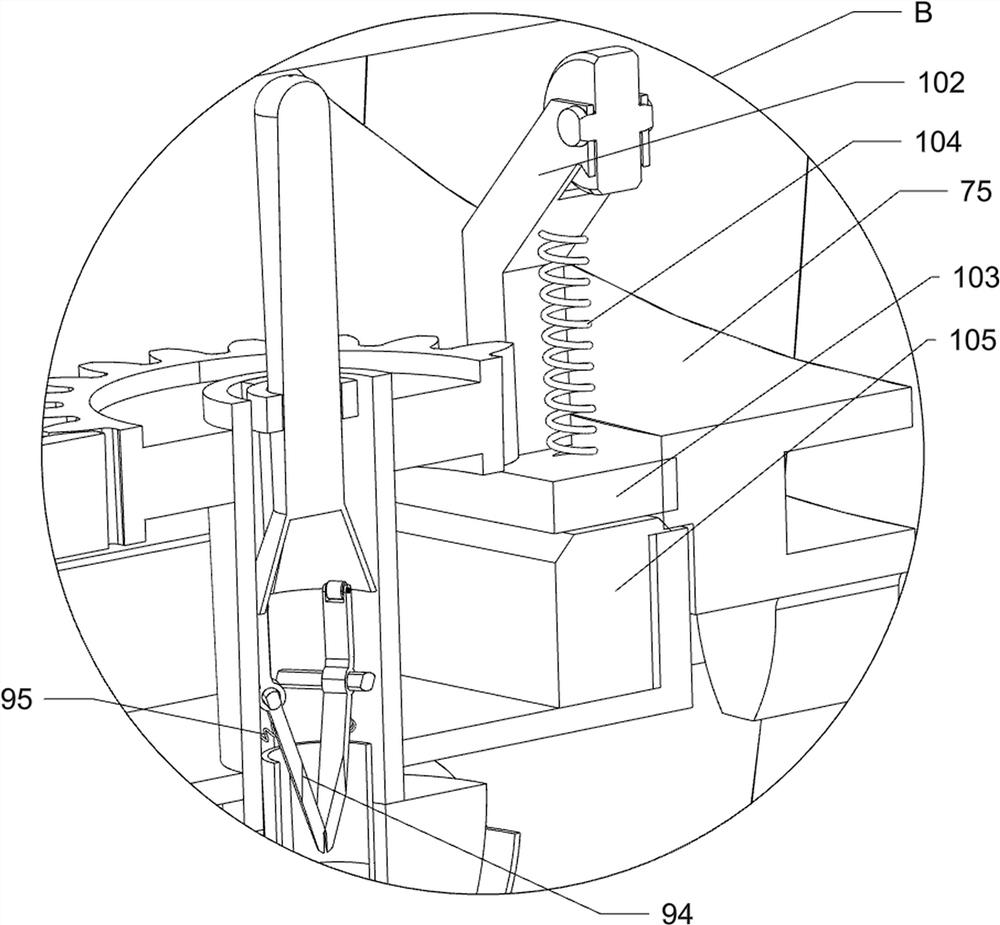
[0032] On the basis of Example 1, such as Figure 2-Figure 5 As shown, a clamping mechanism 9 is also included, and the clamping mechanism 9 includes an arc-shaped contact plate 91, a slide bar 92, a fixed ring 93, a clamping bar 94 and a first spring 95, and the outer circumference of the annular tube 5 is affixed to the left There is an arc-shaped contact plate 91, and the inner side of the hollow placement rod 82 is fixedly connected with a fixed ring 93, and a slide rod 92 is slidably connected in the fixed ring 93. The slide rod 92 cooperates with the arc-shaped contact plate 91, and the hollow placement rod 82 There are three clamping rods 94 evenly spaced on the inside circumference, and the inner end of the clamping rods 94 is positioned at the inside of the slide bar 92 to cooperate with it.
[0033] Also include a pusher mechanism 10, the pusher mechanism 10 includes an arc trigger plate 101, an n-type rod 102, a first strong magnet 103, a second spring 104 and a sec...
Embodiment 3
[0037] On the basis of embodiment 1 and embodiment 2, such as Figure 1-Figure 3 As shown, it also includes an arc-shaped fixing plate 11, a connecting rod 12 and an arc-shaped limiting plate 13, the upper part of the left side of the support plate 2 is fixedly connected with an arc-shaped fixing plate 11, and the inner surface of the arc-shaped fixing plate 11 is uniformly spaced. Connecting rod 12 is connected, and arc-shaped limiting plate 13 is fixedly connected between all connecting rods 12 inner ends on each side, and arc-shaped limiting plate 13 cooperates with u-shaped clamping plate 81.
[0038] Also comprise mounting plate 14, guide shaft 15 and the 3rd spring 16, u-shaped plate 3 outer left front and rear symmetrically fixedly be equipped with mounting plate 14, be fixed with guide shaft 15 between the mounting plate 14 of front and rear sides, guide shaft 15 runs through the left part of the arc-shaped friction plate 4 to slide with it, and the third spring 16 is ...
PUM
 Abstract
Description
Claims
Application Information
 - R&D Engineer
- R&D Manager
- IP Professional
- Industry Leading Data Capabilities
- Powerful AI technology
- Patent DNA Extraction
Browse by: Latest US Patents, China's latest patents, Technical Efficacy Thesaurus, Application Domain, Technology Topic, Popular Technical Reports.
© 2024 PatSnap. All rights reserved.Legal|Privacy policy|Modern Slavery Act Transparency Statement|Sitemap|About US| Contact US: help@patsnap.com