Glycerin fructose canning machine for neurosurgery
A neurosurgery and canning technology, which is applied in the field of neurosurgery glycerin fructose canning machines, can solve the problems of low canning efficiency and cumbersome procedures, and achieve the effect of improving accuracy
- Summary
- Abstract
- Description
- Claims
- Application Information
AI Technical Summary
Problems solved by technology
Method used
Image
Examples
Embodiment 1
[0069] A neurosurgical glycerol fructose canning machine, such as figure 1 As shown, it includes a bottom plate 1, a support plate 2, a canning mechanism 3 and a liquid replenishing mechanism 4. The top right side of the bottom plate 1 is provided with a canning mechanism 3, the top right side of the bottom plate 1 is provided with a liquid replenishing mechanism 4, and the top of the bottom plate 1 is provided with a liquid replenishing mechanism 4. There are support plates 2.
[0070] When the glycerin fructose needs to be canned, the staff can place the can on the support plate 2, and then start the canning mechanism 3 to move downward, and the downward movement of the canning mechanism 3 drives the liquid replenishment mechanism 4 to move downward, thereby filling The tank mechanism 3 squeezes the glycerol fructose into the tank to complete the canning work, and then the staff takes out the canned tank for the next step.
Embodiment 2
[0072] On the basis of Example 1, as Figure 2-Figure 3 As shown, the canning mechanism 3 includes an L-shaped rod 30, a cylinder 31, a piston 32, a hollow cylinder 33 and a rubber plug 34, an L-shaped rod 30 is provided on the right side of the top of the bottom plate 1, and a cylinder is provided at the upper left end of the L-shaped rod 30. 31. The end of the cylinder 31 is provided with a piston 32, the liquid replenishing mechanism 4 is provided with a hollow cylinder 33, the piston 32 is located in the hollow cylinder 33 and is slidingly matched with the hollow cylinder 33, and a rubber plug 34 is provided around the lower part of the hollow cylinder 33.
[0073] The liquid replenishing mechanism 4 includes a bracket 40, a first sliding rail 41, a liquid box 42, a feeding pipe 43 and a first elastic member 44. Two brackets 40 are arranged on the top of the bottom plate 1, and a first sliding rail is arranged on the top of the brackets 40. 41. A liquid box 42 is slidably ...
Embodiment 3
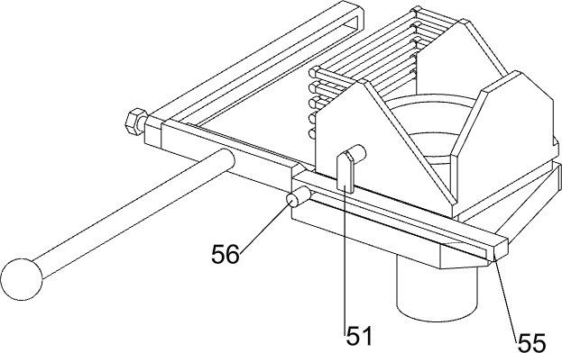
[0076] On the basis of Example 2, as Figure 4-Figure 5 As shown, it also includes a loading mechanism 5. The loading mechanism 5 includes a support column 50, a support rod 51, a second slide rail 52, a push plate 53, a material box 54, a guide rod 55 and a push plate 56. The top of the bottom plate 1 The rear side is provided with a pillar 50, the rear side of the support plate 2 is provided with a guide rod 55, the top of the guide rod 55 is provided with a support rod 51, the support rod 51 is provided with a material box 54, and a pusher plate 56 is slidably connected to the guide rod 55. The pushing plate 56 is located at the bottom of the material box 54 , a second sliding rail 52 is provided on the right side of the top of the support plate 2 , and a pushing plate 53 is slidably connected to the second sliding rail 52 .
[0077] The staff can put a certain amount of cans into the material box 54, and then push the push plate 56 to move to the right, thereby driving the...
PUM
 Abstract
Description
Claims
Application Information
 - R&D
- Intellectual Property
- Life Sciences
- Materials
- Tech Scout
- Unparalleled Data Quality
- Higher Quality Content
- 60% Fewer Hallucinations
Browse by: Latest US Patents, China's latest patents, Technical Efficacy Thesaurus, Application Domain, Technology Topic, Popular Technical Reports.
© 2025 PatSnap. All rights reserved.Legal|Privacy policy|Modern Slavery Act Transparency Statement|Sitemap|About US| Contact US: help@patsnap.com


