
Unmanned aerial vehicle for aerial photography

An aerial photography and unmanned aerial vehicle technology, applied in air transportation, rotorcraft, motor vehicles, etc., can solve the problems of shortening the service life, short circuit, easy to wear and so on, and achieve the effect of reducing shaking, preventing wear and prolonging the service life.

Active Publication Date: 2021-04-09
淮北九天测绘股份有限公司
View PDF13 Cites 1 Cited by
  • Summary
  • Abstract
  • Description
  • Claims
  • Application Information

AI Technical Summary

Problems solved by technology

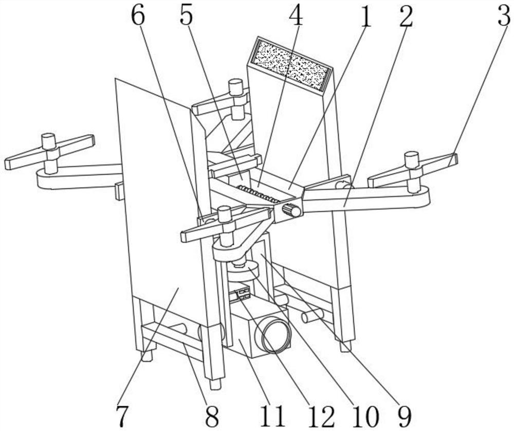
In terms of civilian use, drones + industry applications are the real rigid needs of drones; currently, they are used in aerial photography, agriculture, plant protection, micro selfies, express delivery, disaster relief, wildlife observation, infectious disease monitoring, surveying and mapping, news reports, power patrols, etc. Inspection, disaster relief, film and television shooting, romantic manufacturing and other fields have greatly expanded the use of drones themselves. Developed countries are also actively expanding industry applications and developing drone technology. The existing drones for aerial photography When in use, it is easily affected by the wind and shakes, causing the camera to swing randomly and be damaged, and it does not have the function of shielding the rain in rainy days, which may easily cause the drone to enter water and short circuit. At the same time, the camera lens of the drone is not used for a long time. Exposure to the external environment is prone to wear and tear, shortening service life

Method used


Image

  • Unmanned aerial vehicle for aerial photography
  • Unmanned aerial vehicle for aerial photography
  • Unmanned aerial vehicle for aerial photography

Examples


Embodiment Construction

[0028] In order to make the technical means, creative features, goals and effects achieved by the present invention easy to understand, the present invention will be further described below in conjunction with specific embodiments.

[0029] In the description of the present invention, it should be noted that the terms "upper", "lower", "inner", "outer", "front end", "rear end", "both ends", "one end", "another end" The orientation or positional relationship indicated by etc. is based on the orientation or positional relationship shown in the drawings, and is only for the convenience of describing the present invention and simplifying the description, rather than indicating or implying that the referred device or element must have a specific orientation, use a specific Azimuth configuration and operation, therefore, should not be construed as limiting the invention. In addition, the terms "first" and "second" are used for descriptive purposes only, and should not be understood ...


PUM


Abstract

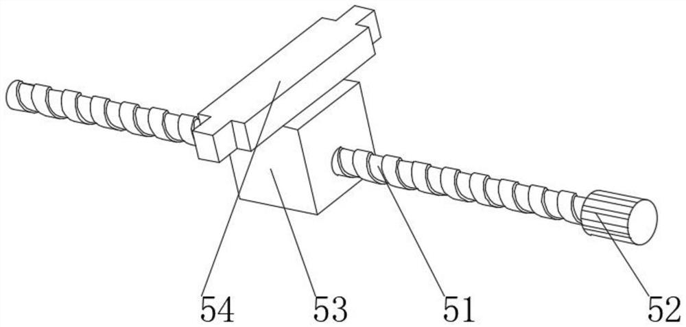
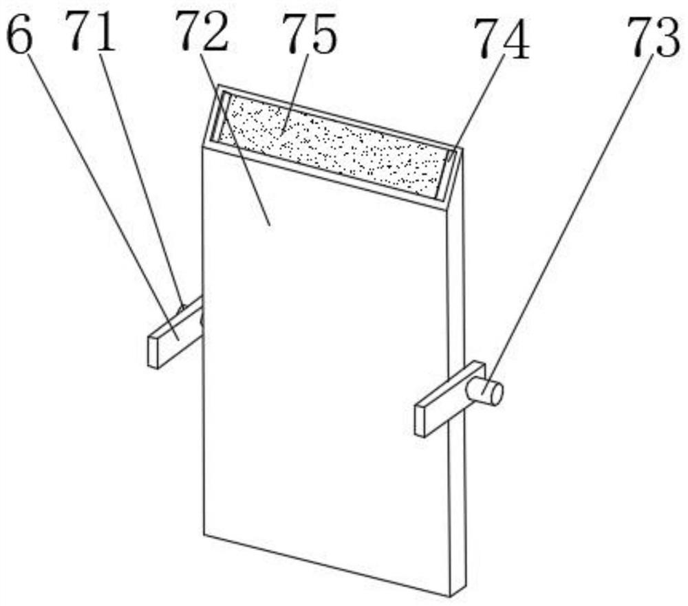
The invention discloses an unmanned aerial vehicle for aerial photography. The unmanned aerial vehicle comprises a body, the front side and the rear side of the left end of the body and the front side and the rear side of the right end of the body are each fixedly provided with a support, the upper ends of the two supports are each movably connected with a rotor wing, a sliding groove is formed in the middle of the upper end of the body, and a sliding balance device is arranged on the groove wall of the sliding groove; the opposite faces of two fixing plates are jointly provided with a rain shielding device, the lower ends of two rain shielding devices are each provided with a clamping device, a rotating device is arranged in the middle of the lower end of the body, a telescopic protection device is arranged at the top of an inner cavity of the rotating device, and a photographic device is arranged on the lower portion of the inner cavity of the rotating device; and a host device is arranged at the rear part of the upper end of the photographic device. According to the unmanned aerial vehicle for aerial photography, a balance block plays a role in balancing the body when sliding forwards or backwards, shaking of the photographic device is reduced, and the photographic device is protected.

Description

technical field [0001] The invention relates to the field of unmanned aerial vehicles, in particular to an aerial photography unmanned aerial vehicle. Background technique [0002] Unmanned aircraft is referred to as "unmanned aerial vehicle", and the English abbreviation is "UAV". Drones are often better suited for missions that are too "dumb, dirty or dangerous" than manned aircraft. According to the application field, UAV can be divided into military and civilian. In terms of military use, UAVs are divided into reconnaissance aircraft and target aircraft. In terms of civilian use, drones + industry applications are the real rigid needs of drones; currently, they are used in aerial photography, agriculture, plant protection, micro selfies, express delivery, disaster relief, wildlife observation, infectious disease monitoring, surveying and mapping, news reports, power patrols, etc. Inspection, disaster relief, film and television shooting, romantic manufacturing and oth...

Claims


Application Information

Patent Timeline
Patent Type & Authority Applications(China)
IPC IPC(8): B64C27/08B64D47/08
CPCB64C27/08B64D47/08Y02T50/60
Inventor 陈超董永飞沙鸿汛
Owner 淮北九天测绘股份有限公司
Learn More