Power conversion mechanism of wind energy storage hybrid power device of new energy vehicle
A new energy vehicle and hybrid technology, applied in the conversion of air flow to electric energy, energy storage, wind power engine, etc.
- Summary
- Abstract
- Description
- Claims
- Application Information
AI Technical Summary
Problems solved by technology
Method used
Image
Examples
specific Embodiment approach 1
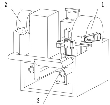
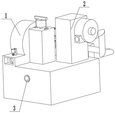
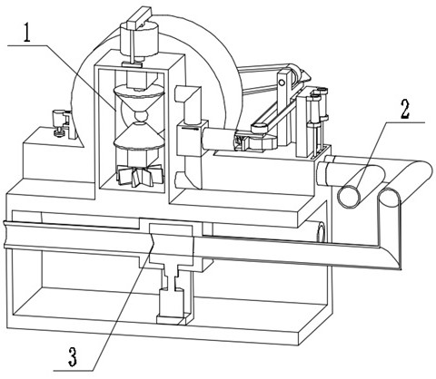
[0030]Bonded belowfigure 1 ,figure 2 ,image 3 ,Figure 4 ,Figure 5 ,Figure 6 ,Figure 7 ,Figure 8 ,Figure 9 ,Figure 10 ,Figure 11 ,Figure 12 ,Figure 13 ,Figure 14 ,Figure 15 ,Figure 16 ,Figure 17In the present embodiment, the present invention relates to a wind energy savings device, more specifically a power conversion mechanism for a new energy vehicle wind energy savings hybrid device, the new energy vehicle wind energy savings hybrid device, a total of power converting mechanisms 1, Output mechanism 2, wind switching mechanism 3, and the device can control the air supply, the device can convert the wind energy into electrical energy, and ensure the stable operation of the equipment, the device can utilize air to advance, and the device can use air to assist the brakes.
[0031]The power conversion mechanism 1 is connected to the output mechanism 2, and the power conversion mechanism 1 is connected to the wind switching mechanism 3.
specific Embodiment approach 2
[0033]Bonded belowfigure 1 ,figure 2 ,image 3 ,Figure 4 ,Figure 5 ,Figure 6 ,Figure 7 ,Figure 8 ,Figure 9 ,Figure 10 ,Figure 11 ,Figure 12 ,Figure 13 ,Figure 14 ,Figure 15 ,Figure 16 ,Figure 17In the present embodiment, the present embodiment further illustrates the embodiment, the power conversion mechanism 1 including the base 1-1, the first air tube 1-2, the second air tube 1-3, the wind box 1- 4, gate groove 1-5, gate 1-6, hydraulic rod 1-7, belt shaft cam 1-8, bearing seat 1-9, pulley 1-10, belt 1-11, with rod fittings 1-12, Hydraulic cylinder 1-13, hydraulic cylinder support seat 1-14, tube tube 1-15, connect tube 1-16, oil tank 1-17, support seat 1-18, magnetic field 1-19, pulley wheel I1-20, bearing housing I1-21, belt shaft cone gear 1-22, transmission belt 1-23, pulley II1-24, belt bearing gear I1-25, pulley III1-26, spring 1-27, lock thread Rod 1-28, a threaded hole fixing seat 1-29, a threaded hole cover 1-30, an insertion tank 1-31, air outlet 1-32, circular air outlet ...
specific Embodiment approach 3
[0035]Bonded belowfigure 1 ,figure 2 ,image 3 ,Figure 4 ,Figure 5 ,Figure 6 ,Figure 7 ,Figure 8 ,Figure 9 ,Figure 10 ,Figure 11 ,Figure 12 ,Figure 13 ,Figure 14 ,Figure 15 ,Figure 16 ,Figure 17In the present embodiment, the present embodiment will further explain the embodiment, the output mechanism 2 includes a bend 2-1, a protective box 2-2, a power output shaft 2-3, a power motor 2-4, an air outlet 2 -5, the power impeller 2-6, the elbow 2-1 is connected to the first air tube 1-2, and the elbow 2-1 is connected to the protective case 2-2 and in communication, the protective box 2-2 and the power output shaft 2 -3 Turn connection, the power output shaft 2-3 is connected to the power motor 2-4, the power motor 2-4 is connected to the base 1-1, the protective box 2-2 is connected to the power motor 2-4, and the air outlet 2-5 Set on the protective box 2-2, the power impeller 2-6 is connected to the power output shaft 2-3.
PUM
 Abstract
Description
Claims
Application Information
 - R&D Engineer
- R&D Manager
- IP Professional
- Industry Leading Data Capabilities
- Powerful AI technology
- Patent DNA Extraction
Browse by: Latest US Patents, China's latest patents, Technical Efficacy Thesaurus, Application Domain, Technology Topic, Popular Technical Reports.
© 2024 PatSnap. All rights reserved.Legal|Privacy policy|Modern Slavery Act Transparency Statement|Sitemap|About US| Contact US: help@patsnap.com


