Storage cabinet for placing precise instruments

A technology for precision instruments and storage cabinets, applied in the field of storage cabinets, can solve the problems of knocking down the instruments, increasing the labor intensity of staff, damage, etc., and achieving the effect of realizing the card position

Inactive Publication Date: 2021-04-09
JIANGXI EQUIP INDAL GROUP GREAT INSURANCENT
View PDF4 Cites 1 Cited by
  • Summary
  • Abstract
  • Description
  • Claims
  • Application Information

AI Technical Summary

Problems solved by technology

[0002] In chemical and medical laboratories, for the convenience of experiments, a partition frame is installed on the test bench to store reagents or instruments. The partition frame has no cover, and if it is stored for a long time, the kits and instruments will be covered with dust. Therefore, it is necessary to clean the laboratory bench from time to time, which increases the labor intensity of the staff, and when storing glass instruments, care must be taken, otherwise it will knock down the nearby instruments and cause damage

Method used


Image

  • Storage cabinet for placing precise instruments
  • Storage cabinet for placing precise instruments
  • Storage cabinet for placing precise instruments

Examples


Embodiment 1

[0066] A storage cabinet for storing precision instruments, such as Figure 1-3 As shown, it includes a cabinet body 1, a tripod 2, a door panel mechanism 3 and a lifting frame mechanism 4. The left and right sides of the lower part of the cabinet body 1 are provided with a tripod frame 2, the front side of the cabinet body 1 is provided with a door panel mechanism 3, and the cabinet body 1 A lifting frame mechanism 4 is arranged between the inside and the door panel mechanism 3 .

[0067] Door panel mechanism 3 comprises slider frame 31, connecting plate 32, sliding door panel 33, first spring 34, handle 35 and guide plate 36, and cabinet body 1 front portion left and right sides all slides and is connected with slider frame 31, and slider A connecting plate 32 is connected to the frame 31, and a sliding door panel 33 is slidably connected between the front sides of the connecting plate 32, and a first spring is arranged between the left and right sides of the rear part of th...

Embodiment 2

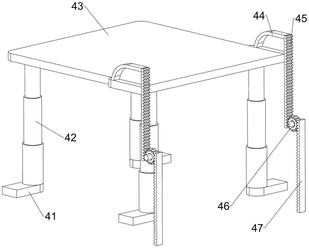
[0071] On the basis of Example 1, such as Figure 4-7 As shown, a top cover mechanism 5 is also included, and the top cover mechanism 5 includes a mounting seat 51, a connecting seat 52, a casing 53, a tooth block ring 54, a third rack frame 55 and a support frame 56, and the outer wall of the upper part of the cabinet body 1 is left and right Both sides are connected with two mounting seats 51, and the mounting seats 51 are connected with a connecting seat 52, and the connecting seats 52 on the same side are connected with a shell 53 in a rotational manner, and the inner side of the shell 53 is connected with a tooth block ring on both sides. 54, the left and right sides of the first placement plate 43 are provided with two third rack racks 55, the third rack rack 55 is engaged with the tooth block ring 54, and the left and right sides of the upper part of the cabinet body 1 are provided with brackets 56. The frame 56 is attached to the casing 53 .

[0072] The first placing...


PUM


Abstract

The invention relates to a storage cabinet, and particularly relates to a storage cabinet for placing precise instruments. The technical problem is to provide a storage cabinet for placing precise instruments, wherein the storage cabinet can realize automatic lifting, has a protection function and is not easy to knock down. According to the technical scheme, the storage cabinet for placing the precise instruments comprises a cabinet body, foot stools, a door plate mechanism and a lifting frame mechanism, wherein the foot stools are arranged on the two sides of the cabinet body; the door plate mechanism is arranged on one side of the cabinet body; and the lifting frame mechanism is arranged between the interior of the cabinet body and the door plate mechanism. Through cooperation between the door plate mechanism and the lifting frame mechanism, the precise instrument can be freely stored and taken out, and the shielding effect on the precise instrument is achieved.

Description

technical field [0001] The invention relates to a storage cabinet, in particular to a storage cabinet for storing precision instruments. Background technique [0002] In chemical and medical laboratories, for the convenience of experiments, a partition frame is installed on the test bench to store reagents or instruments. The partition frame has no cover, and if it is stored for a long time, the kits and instruments will be covered with dust. Therefore, it is necessary to clean the laboratory bench from time to time, which increases the labor intensity of the staff, and when storing glass instruments, care must be taken, otherwise it will knock down the nearby instruments and cause damage. [0003] In order to solve the above problems, a kind of storage cabinet for placing precision instruments that can realize automatic lifting, has protection, and is not easy to be knocked down is developed now. Contents of the invention [0004] In order to overcome the shortcoming of ...

Claims


Application Information

Patent Timeline
Patent Type & Authority Applications(China)
IPC IPC(8): B01L1/00
CPCB01L1/00
Inventor 徐迪
Owner JIANGXI EQUIP INDAL GROUP GREAT INSURANCENT
Why Eureka
Try Eureka