Portable clinical monitor for neurology department
A neurology and monitor technology, applied in the field of neurology, can solve the problems of unstable monitoring data of the monitoring device, inconvenient support and movement of the monitoring device, and inability to intuitively observe the state of relaxation or tension
- Summary
- Abstract
- Description
- Claims
- Application Information
AI Technical Summary
Problems solved by technology
Method used
Image
Examples
Embodiment 1
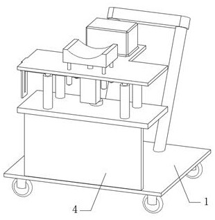
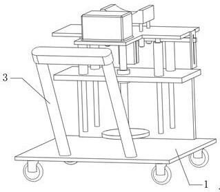
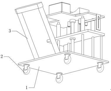
[0033] see Figure 1-8 As shown, a portable neurology clinical monitor includes a device base plate 1, universal wheels 2 are fixedly installed at the four corners of the bottom of the device base plate 1, a push handle 3 is fixedly connected to the top of the device base plate 1, and the top of the device base plate 1 is fixed. Connected with a stand plate 4, the top of the stand plate 4 is fixedly connected with a support plate 5, the top of the support plate 5 is fixedly connected with a nut seat 6, the axis of the nut seat 6 is threaded with a screw rod 7, and the top of the screw rod 7 rotates The lifting plate 8 is connected, the bottom four corners of the lifting plate 8 are fixedly connected with the first limit rod 802, the top four corners of the support plate 5 are fixedly connected with the first limit tube 803, and the first limit rod 802 is movably inserted in the In the first limit tube 803, the bottom of the screw mandrel 7 passes through the nut seat 6 and the...
Embodiment 2
[0042] see Figure 1-8 As shown, a portable neurology clinical monitor includes a device base plate 1, universal wheels 2 are fixedly installed at the four corners of the bottom of the device base plate 1, a push handle 3 is fixedly connected to the top of the device base plate 1, and the top of the device base plate 1 is fixed. Connected with a stand plate 4, the top of the stand plate 4 is fixedly connected with a support plate 5, the top of the support plate 5 is fixedly connected with a nut seat 6, the axis of the nut seat 6 is threaded with a screw rod 7, and the top of the screw rod 7 rotates The lifting plate 8 is connected, the bottom four corners of the lifting plate 8 are fixedly connected with the first limit rod 802, the top four corners of the support plate 5 are fixedly connected with the first limit tube 803, and the first limit rod 802 is movably inserted in the In the first limit tube 803, the bottom of the screw rod 7 passes through the nut seat 6 and the sup...
PUM
 Abstract
Description
Claims
Application Information
 - Generate Ideas
- Intellectual Property
- Life Sciences
- Materials
- Tech Scout
- Unparalleled Data Quality
- Higher Quality Content
- 60% Fewer Hallucinations
Browse by: Latest US Patents, China's latest patents, Technical Efficacy Thesaurus, Application Domain, Technology Topic, Popular Technical Reports.
© 2025 PatSnap. All rights reserved.Legal|Privacy policy|Modern Slavery Act Transparency Statement|Sitemap|About US| Contact US: help@patsnap.com


