Local control cabinet capable of supplying power to multiple control cabinets

A control cabinet and controller technology, applied in the field of control cabinets, can solve the problems of reducing the maintenance efficiency of the controller, winding connection lines, poor practicability, etc., achieving the effects of better practicability, preventing winding, and improving maintenance efficiency

Active Publication Date: 2021-04-06
山东万盛电气有限公司
View PDF17 Cites 2 Cited by
  • Summary
  • Abstract
  • Description
  • Claims
  • Application Information

AI Technical Summary

Problems solved by technology

[0003] The purpose of the present invention is to provide an on-site control cabinet capable of supplying power to multiple control cabinets, which has the advantages of convenient wiring, which is convenient for distinguishing connecting lines, prevents connecting lines from being entangled at the socket, avoids plugging and unplugging errors by users, and improves wiring accuracy , simple structure, easy to use, no need to dismantle the cabinet during maintenance, and no need to plug or unplug any connecting wires, which effectively improves the maintenance efficiency and has the advantages of better practicability, so as to solve the wiring confusion caused by the wiring proposed in the above background technology, The connecting lines are easily entangled at the wiring structure, which is inconvenient to use, and the existing local control cabinet needs to unplug all the connecting lines during maintenance, and after the maintenance is completed, each connecting line needs to be plugged in again, which is time-consuming and laborious , which greatly reduces the maintenance efficiency of the controller and the problem of poor practicability

Method used


Image

  • Local control cabinet capable of supplying power to multiple control cabinets
  • Local control cabinet capable of supplying power to multiple control cabinets
  • Local control cabinet capable of supplying power to multiple control cabinets

Examples


Embodiment Construction

[0022] The technical solutions in the embodiments of the present invention will be clearly described in conjunction with the accompanying drawings in the embodiments of the present invention; it is obvious that the described embodiments are only a part of the embodiments of the present invention, not all embodiments, based on The embodiments of the present invention and all other embodiments obtained by persons of ordinary skill in the art without making creative efforts belong to the protection scope of the present invention.

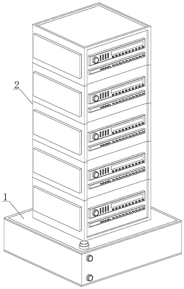
[0023] see figure 1 , an on-site control cabinet capable of supplying power to multiple control cabinets, including a control cabinet base 1 and a control cabinet mechanism 2, the position of the control cabinet mechanism 2 is limited by the control cabinet base 1, and the area of ​​the control cabinet base 1 Larger, when the superimposed control cabinet mechanism 2 is stacked on the control cabinet base 1, the overall position of the device is more st...


PUM


Abstract

The invention relates to the technical field of control cabinets, in particular to a local control cabinet capable of supplying power to multiple control cabinets, which comprises a control cabinet base and a control cabinet mechanism, wherein the control cabinet mechanism is formed by splicing a plurality of control cabinets, the bottommost control cabinet is connected with the control cabinet base, and the stacked control cabinets are independent of each other. During use, the connecting surface of the control cabinet can be selected to face one side of a connected device according to the position and orientation of the connected device, wiring is facilitated, the positions of connecting lines are limited through the line fixing frames during wiring, each line fixing frame corresponds to one socket structure, the connecting lines are distinguished conveniently, connecting lines are prevented from being wound at sockets, wrong user plugging is avoided, the wiring accuracy is improved, and the power-on and connection states of the controller can be controlled by moving the stretching plate during maintenance, the structure is simple, the use is convenient, the cabinet body does not need to be dismounted during maintenance, any connecting wire does not need to be plugged, the maintenance efficiency is effectively improved, and the practicability is better.

Description

technical field [0001] The invention relates to the technical field of control cabinets, in particular to an on-site control cabinet capable of supplying power to multiple control cabinets. Background technique [0002] The on-site control cabinet is a control cabinet installed on the work site to complete the on-site operation of the controlled object. Since there are many devices connected to the on-site control cabinet, usually one on-site control cabinet is equipped with multiple sets of wiring structures. The interface is connected to the controller installed inside the local control cabinet to realize the connection between the controller and the controlled equipment. Since the installation and placement of each controlled device are different, most of the existing local control cabinet wiring structures are It is installed on the same surface, so it is easy to cause wiring confusion during wiring, and the connecting lines are easy to be entangled at the wiring structu...

Claims


Application Information

Patent Timeline
Patent Type & Authority Applications(China)
IPC IPC(8): H05K5/00H05K5/02
CPCH05K5/0021H05K5/0217H05K5/0247
Inventor 谢鸿斌
Owner 山东万盛电气有限公司
Why Eureka
Try Eureka