Agricultural automatic drying facility with stable discharging structure

A technology for stable discharge and agricultural tools, which is applied in the direction of grain drying, drying solid materials, drying chambers/containers, etc., and can solve the problems affecting the smoothness of equipment discharge, affecting the drying efficiency of corn cobs, and easy blockage of corn cobs. problems, to achieve the effect of ensuring smooth stability, ensuring the stability of the material, and ensuring the stability

Inactive Publication Date: 2021-04-06
林映辉
View PDF11 Cites 0 Cited by
  • Summary
  • Abstract
  • Description
  • Claims
  • Application Information

AI Technical Summary

Problems solved by technology

[0008] The purpose of the present invention is to provide an automatic drying equipment with a stable discharge structure for agriculture, so as to solve the corn cob drying device in the prior art proposed in the above-mentioned background technology, which is affected by the elongated corn cob when it is working. , leading to the easy blockage of corn cob cutting, which affects the smoothness of equipment discharge, and when the equipment is working, the internal corn cobs are stacked tightly as a whole, which affects the drying efficiency of corn cobs

Method used


Image

  • Agricultural automatic drying facility with stable discharging structure
  • Agricultural automatic drying facility with stable discharging structure
  • Agricultural automatic drying facility with stable discharging structure

Examples


Embodiment Construction

[0036] The following will clearly and completely describe the technical solutions in the embodiments of the present invention with reference to the accompanying drawings in the embodiments of the present invention. Obviously, the described embodiments are only some, not all, embodiments of the present invention. Based on the embodiments of the present invention, all other embodiments obtained by persons of ordinary skill in the art without making creative efforts belong to the protection scope of the present invention.

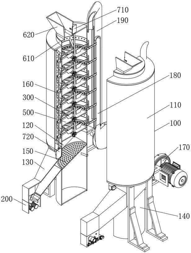
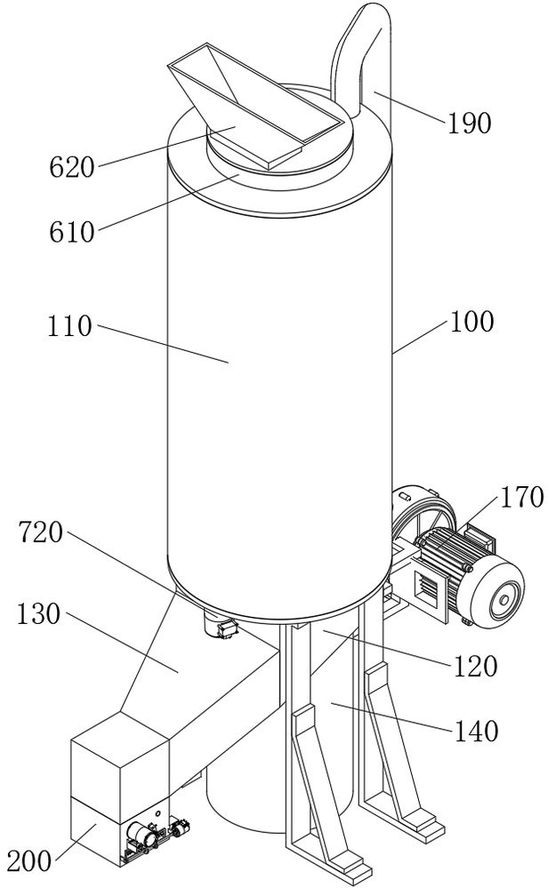
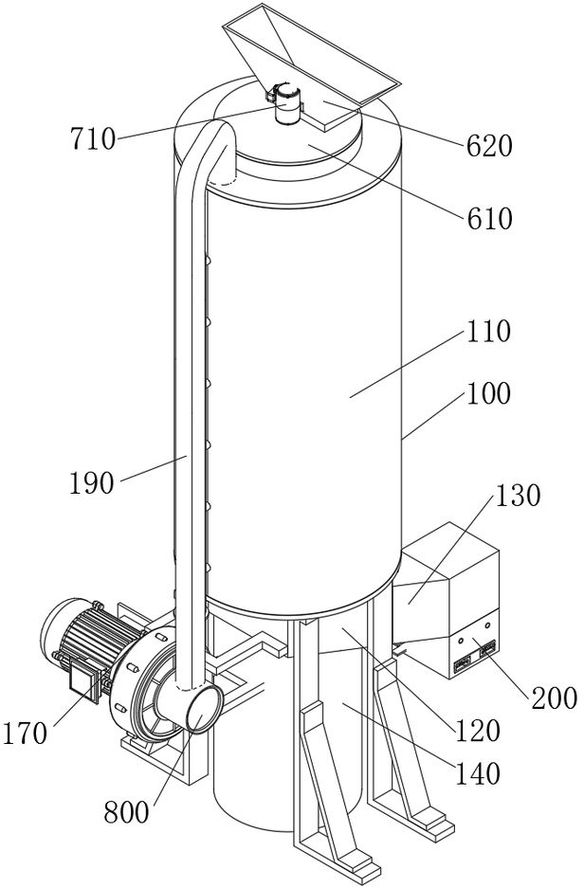
[0037] see Figure 1-9 , an embodiment provided by the present invention: an agricultural automatic drying equipment with a stable discharge structure, including a drying mechanism 100, the drying mechanism 100 includes an outer cylinder 110, and the bottom of the outer cylinder 110 is fixedly welded with a bottom bin 120 , the front of the bottom bin 120 is fixedly welded with a guide bin 130, and the position below the front of the guide bin 130 is fixedly i...


PUM


Abstract

The invention relates to the technical field of crop drying equipment, in particular to an agricultural automatic drying facility with a stable discharging structure. The facility comprises a drying mechanism, wherein the drying mechanism comprises an outer cylinder, a bottom bin is fixedly welded to the bottom of the outer cylinder, a guide bin is fixedly welded to the obverse side of the bottom bin, a discharging mechanism is fixedly installed at the bottom of the obverse side of the guide bin, the discharging mechanism comprises a discharging bin, and the discharging bin is welded to the bottom of the obverse side of the guide bin in a communicating mode. According to the agricultural automatic drying facility, the discharging mechanism is arranged and installed at the bottom of the obverse side of the guide bin, by means of synchronous same-direction rotation of two rubber rollers arranged on the upper portion of the interior of the discharging bin and rotary stirring operation of the two rubber rollers, corn cobs which are transversely arranged inside the discharging bin can be erected, the two rubber rollers cooperate with the synchronous relative rotation of two output rollers located below the rubber rollers, , stable extrusion conveying is conducted, the corn cobs are effectively prevented from being clamped inside the discharging bin, and the smoothness stability of the facility in the discharging process is effectively guaranteed.

Description

technical field [0001] The invention relates to the technical field of crop drying equipment, in particular to an automatic drying equipment for agriculture with a stable discharge structure. Background technique [0002] With the development and progress of science and technology, people's technology in the field of agricultural planting is becoming more and more mature, and the yield of crops is also increasing. In agricultural planting, corn, as a high-yield crop, has strong cold resistance and drought resistance. As an excellent food crop, it is often widely used as feed raw materials and national grain storage. Affected by the characteristics of corn, the inside of mature corn is usually moist. In order to ensure that the mature corn is stored in a high-quality state, it is usually necessary to The corn is dried to remove the moisture in the corn and avoid the corn being corroded by moisture during the storage process, so as to prolong the storage time of the corn. In t...

Claims


Application Information

Patent Timeline
Patent Type & Authority Applications(China)
IPC IPC(8): F26B11/14F26B21/02F26B25/02F26B25/04F26B25/18B07B1/00
CPCF26B11/14F26B21/001F26B21/02F26B25/02F26B25/04F26B25/18B07B1/00F26B2200/06
Inventor 林映辉
Owner 林映辉
Why Eureka
Try Eureka