
Air-conditioning system and control method thereof

A technology of air conditioning system and control method, which is applied in the directions of air conditioning system, space heating and ventilation, refrigerator, etc., which can solve the problems of poor heating efficiency, inability to balance the defrosting effect and heating efficiency of the air conditioning system, and achieve easy assembly and solution It is difficult to balance the defrosting effect and heating efficiency, and the effect of high heating efficiency

Pending Publication Date: 2021-04-06
GREE ELECTRICHEFEI +1
View PDF0 Cites 0 Cited by
  • Summary
  • Abstract
  • Description
  • Claims
  • Application Information

AI Technical Summary

Problems solved by technology

Since the total amount of heat exchange medium in the air conditioning system is constant, the flow rate of the heat exchange medium flowing into the heat releasing component is negatively correlated with the flow rate of the heat exchange medium flowing into the outdoor heat exchanger, which leads to the air conditioning system The better the defrosting effect on the outdoor heat exchanger, the worse the indoor heating efficiency. For this reason, the existing air conditioning system does not improve its defrosting of the outdoor heat exchanger by sacrificing some heating efficiency. The frost effect is to improve the heating efficiency of the room by sacrificing some defrosting effects, which cannot balance the defrosting effect and heating efficiency of the air conditioning system at all.

Method used


Image

  • Air-conditioning system and control method thereof

Examples


Embodiment Construction

[0022] The present invention will be further described below in conjunction with accompanying drawing.

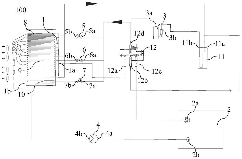
[0023] figure 1 It is a schematic structural diagram of an air conditioning system 100 according to an embodiment of the present invention. Such as figure 1 As shown, the air conditioning system 100 of the embodiment of the present invention mainly includes an outdoor heat exchanger 1, an indoor heat exchanger 2, a compressor 3, an expansion valve 4, a first valve 5, and a second valve 6 for supplying the outdoor heat exchanger. 1 The first heat release member 8 for heating, the second heat release member 9 for heating the outdoor heat exchanger 1 and the temperature measuring sensor for measuring the surface temperature of the outdoor sensor, and the first valve 5 and the second valve 6. A control module electrically connected to the temperature sensor. The compressor 3 is used to compress the heat exchange medium, its outlet is connected to the first port 2a of the ind...


PUM


Abstract

The invention relates to an air-conditioning system and a control method thereof. The air-conditioning system comprises an outdoor heat exchanger, an indoor heat exchanger, a compressor, an expansion valve, a first valve, a second valve, a first heat release component, a second heat release component, a temperature measuring sensor and a control module, wherein the first heat release component and the second heat release component are used for heating the outdoor heat exchanger, the temperature measuring sensor and the control module are used for measuring the surface temperature of an outdoor sensor, an outlet of the compressor is connected with the first valve and the second valve, the first valve and the second valve are connected with the first heat release component and the second heat release component correspondingly, the first heat release component and the second heat release component are both connected with an inlet of the compressor, and the control module can control the on-off state of the first valve and the second valve according to the testing result of the temperature measuring sensor. According to the air-conditioning system, the problem that the defrosting effect and the heating efficiency of the air-conditioning system are difficult to balance can be solved, the outdoor heat exchanger can be safely defrosted, and the higher heating efficiency of the air-conditioning system can be maintained.

Description

technical field [0001] The invention belongs to the technical field of heat exchange equipment, and in particular relates to an air-conditioning system and a control method for the air-conditioning system. Background technique [0002] The air-conditioning system can force heat to flow from the low-temperature medium to the high-temperature medium in a reverse cycle manner, and it only consumes a small amount of electric energy to obtain a large heat supply, so it is generally used as a heating device in winter. Existing air-conditioning systems mainly include an outdoor heat exchanger, an indoor heat exchanger, a compressor, an expansion valve, and heat releasing components for heating the outdoor heat exchanger. Among them, the heat release part is connected with the outlet of the compressor. When the air conditioning system is in heating operation, part of the heat exchange medium flows from the outlet of the compressor into the heat release part and heats the outdoor hea...

Claims


Application Information

Patent Timeline
Patent Type & Authority Applications(China)
IPC IPC(8): F24F1/06F24F1/14F24F1/46F24F11/64F24F11/61F24F11/70F25B13/00F25B41/20F25B47/02
CPCF24F1/06F24F1/14F24F1/46F24F11/64F24F11/61F24F11/70F25B13/00F25B47/02
Inventor 李敏徐蒙甘威杨久子陈锐郭磊
Owner GREE ELECTRICHEFEI
Learn More