
Wire cutting device for communication engineering

A communication engineering and cutting device technology, applied in the field of wire rod cutting devices, can solve the problems of increasing the labor intensity and workload of wire rod cutting, reducing cutting efficiency and engineering efficiency, reducing the efficiency of wire rod fixed-length cutting, etc., achieving strong practicability and creativity , Improve cutting efficiency and reduce labor intensity

Inactive Publication Date: 2021-04-06
山东鲁南大数据产业发展有限公司
View PDF0 Cites 4 Cited by
  • Summary
  • Abstract
  • Description
  • Claims
  • Application Information

AI Technical Summary

Problems solved by technology

[0002] In communication engineering, it is often necessary to cut the wire to a certain length. In the existing technology, the cutting of the wire generally requires manual labor to first measure the length of the wire, and then mark the fixed point on the wire. The existing technology is not only time-consuming and laborious, but also It greatly increases the labor intensity of wire cutting and the workload of preparation in advance, and reduces the efficiency of wire length cutting. In addition, the length of a batch of wires used in communication engineering is often different, so several stages of wire lengths are required. In the fixed-length cutting process, it is necessary to continuously change the length of the wire to measure the cutting, and further the labor intensity of the staff for the fixed-length cutting of the wire reduces the efficiency of cutting and engineering.

Method used


Image

  • Wire cutting device for communication engineering
  • Wire cutting device for communication engineering
  • Wire cutting device for communication engineering

Examples


Embodiment Construction

[0030] The following will clearly and completely describe the technical solutions in the embodiments of the present invention with reference to the accompanying drawings in the embodiments of the present invention. Obviously, the described embodiments are only some, not all, embodiments of the present invention. Based on the embodiments of the present invention, all other embodiments obtained by persons of ordinary skill in the art without making creative efforts belong to the protection scope of the present invention.

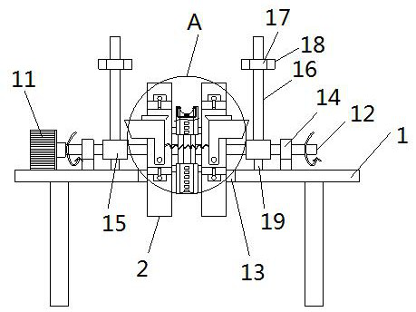
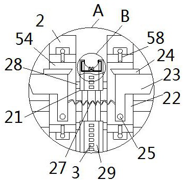
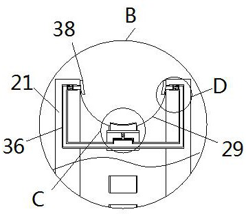
[0031] see Figure 1-8 , the present invention provides a technical solution: a wire cutting device for communication engineering, including a workbench 1, the workbench 1 is a rectangular body, the bottom of the workbench 1 is fixedly equipped with support legs, and the right side of the top of the workbench 1 is fixed A servo motor 11 is installed, and the middle part of the workbench 1 is provided with a through groove 13. The output end on the right side o...


PUM


Abstract

The invention relates to the technical field of wire cutting devices, and discloses a wire cutting device for communication engineering. The wire cutting device comprises a workbench, wherein a servo motor is fixedly arranged at the right side of the top of the workbench; a rotating rod is fixedly connected to the output end of the right side of the servo motor; two sets of rotating plates and a set of limiting plates are arranged in the middle of the outer wall of the rotating rod; and the limiting plates are located between the two rotating plates. According to the wire cutting device for communication engineering, a wire is clamped in clamping grooves of the limiting plates in the front-back horizontal direction, the rotating rod rotates to drive two sets of rotating plates A and rotating plates B to do circular motion at the same time, and two sets of extrusion blocks close to each other drive respective blades to cut the wire on the limiting plates, so that the rotating plates and linkage blocks rotate by a circle to extrude and cut the wire in the clamping grooves once, fixed-length cutting of the wire for communication engineering is achieved, the labor intensity of wire cutting is reduced, and the wire cutting efficiency is improved.

Description

technical field [0001] The invention relates to the technical field of wire cutting devices, in particular to a wire cutting device for communication engineering. Background technique [0002] In communication engineering, it is often necessary to cut the wire to a certain length. In the existing technology, the cutting of the wire generally requires manual labor to first measure the length of the wire, and then mark the fixed point on the wire. The existing technology is not only time-consuming and laborious, but also It greatly increases the labor intensity of wire cutting and the workload of preparation in advance, and reduces the efficiency of wire length cutting. In addition, the length of a batch of wires used in communication engineering is often different, so several stages of wire lengths are required. In the fixed-length cutting process, it is necessary to constantly change the length of the wire to measure the cutting, further reducing the labor intensity of the s...

Claims


Application Information

Patent Timeline
Patent Type & Authority Applications(China)
IPC IPC(8): B21F11/00B21F23/00B21C51/00
CPCB21C51/00B21F11/00B21F23/00
Inventor 高磊王辉高扬李一民
Owner 山东鲁南大数据产业发展有限公司
Learn More