
Positioning tool mold for machining and using method thereof

A technology of mechanical processing and positioning tooling, applied in the field of mechanical processing, can solve the problems of inconvenient mold fixing, inconvenient parts removal, and troublesome parts in the mold, so as to save time and effort in the installation and fixing process, and the installation and fixing of the mold is simple and convenient Effect

Inactive Publication Date: 2021-04-06
沈慧红
View PDF0 Cites 0 Cited by
  • Summary
  • Abstract
  • Description
  • Claims
  • Application Information

AI Technical Summary

Problems solved by technology

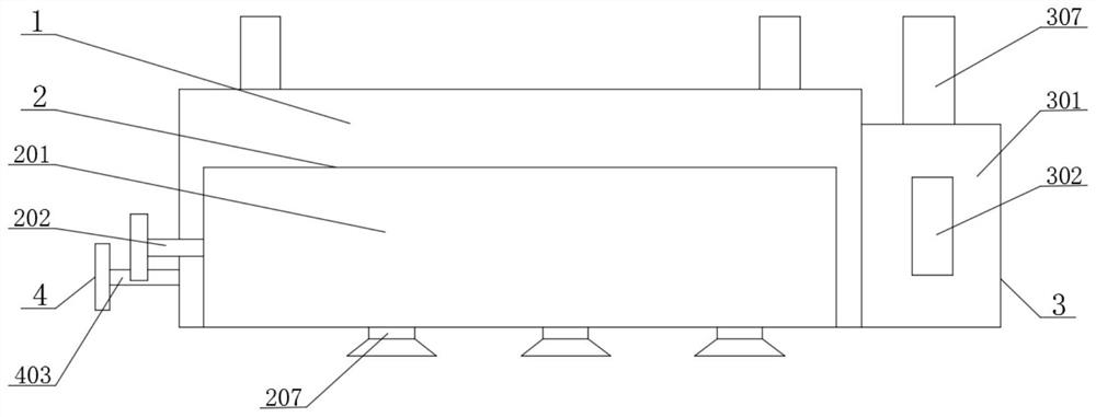
[0002] Molds are various molds and tools used in industrial production for injection molding, blow molding, extrusion, die-casting or forging forming, smelting, stamping, etc. to obtain the required products. In short, molds are tools used to make shaped objects , but there are some problems in the use of some molds now. When using the mold to stamp the parts, in the process of stamping, the staff needs to hold the parts by hand for stamping, and the parts cannot be positioned and fixed. There are potential safety hazards in stamping with parts. At the same time, when stamping parts with molds, it is inconvenient to fix the molds on the workbench. Now one is to use screws to fix the molds. The fixing process is cumbersome and time-consuming. At the same time, after stamping and processing the parts with the mold, it is inconvenient to take out the processed parts in the mold. The process of taking out the parts in the mold is cumbersome, time-consuming and laborious

Method used


Image

  • Positioning tool mold for machining and using method thereof
  • Positioning tool mold for machining and using method thereof
  • Positioning tool mold for machining and using method thereof

Examples


Embodiment 1

[0032]SeeFigure 1-6The present invention provides a technical solution:

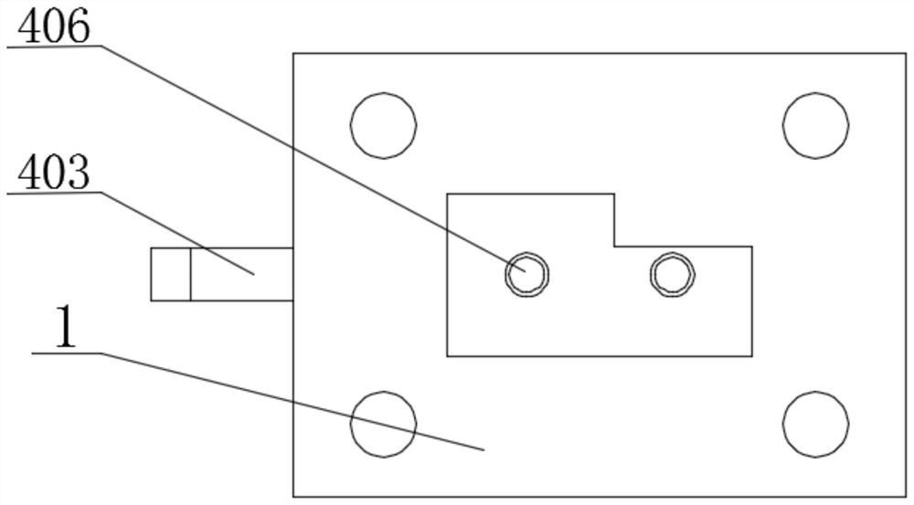
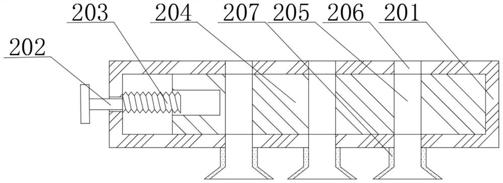
[0033]A mechanical machining positioning tool mold, including the mold body 1, the fixing device 2, the positioning device 3, and the top outfit device 4, the fixing device 2 includes a mounting plate 201, the mounting plate 201 is fixed to the mold body 1, the mounting plate 201 left end face The first handle 202 is rotatably connected to the mounting plate 201, and the first handle 202 is fixed to the first threaded shaft 203, and the first threaded shaft 203 is helically connected to the slide 204, the slide 204 and the mounting plate 201 slide, The inside of the slide 204 is opened with a first hole hole 205, and the top surface of the mounting plate 201 is opened with a second hole hole 206, and the bottom end surface of the mounting plate 201 is connected to the suction cup 207, which is convenient to secure the mold to the workbench.

[0034]The positioning device 3 includes a first positioning plate 301, and...

Embodiment 2

[0037]Embodiment 2 is not described in the same part as in Example 1, seefigure 2 ,image 3 ,Figure 4 ,Figure 5 ,Figure 7 ,Figure 8 withFigure 9 The present invention provides a technical solution:

[0038]The positioning device 3 includes a second positioning plate 308, and the second positioning plate 308 is fixedly coupled to the mold main body 1, and the second positioning plate 308 is fixedly connected to the controller 309, and the inner side fixed connection between the second positioning plate 308 is fixedly connected to multi-stage electric telescopic. The rod 310, the plurality of electric telescoping rod 310 is fixed to the connecting plate 311, and the connecting plate 311 is slidably connected to the second positioning plate 308, and the connecting plate 311 is slidably connected, and the connecting plate 311 is rotated and the rotating rod 312 is connected. The other end of the rotating rod 312 is rotated to be connected to the second pinch plate 313, and the second pinch ...


PUM


Abstract

The invention relates to the field of machining, in particular to a positioning tool mold for machining. The mold comprises a mold body, a fixing device, a positioning device and an ejection device, wherein the fixing device comprises a mounting plate, the mounting plate is fixedly connected with the mold body, the left end surface of the mounting plate is rotatably connected with a first handle, the first handle penetrates through the mounting plate, and the right end surface of the first handle is fixedly connected with a first threaded shaft. According to the mold, through the arrangement of the mounting plate, the first handle and a suction cup, during use, the first handle is rotated to drive the first threaded shaft to rotate, the first threaded shaft rotates to drive a sliding plate to slide, the sliding plate slides to drive a first hole to move, then the first hole, a second hole and the suction cup are staggered, an air inlet channel of the suction cup is closed, then the mold body is pressed, and the mold body can be firmly adsorbed and fixed to a workbench under the action of the suction cup, so that the mold is easy and convenient to install and fix, and time and labor are saved in the installing and fixing process.

Description

Technical field[0001]The present invention relates to the field of machining, in particular a mechanical processing positioning tooling mold and its use.Background technique[0002]The mold is a variety of molds and tools for injection molding, blow molding, extrusion, die-casting or forging, smelting, stamping, or forging molding, smelting, stamping, or forging, smelting, stamping, etc.. In short, the mold is a tool for making forming items. However, some of the models now have some problems, when the replacement is used in the use of the mold, the staff in the process of stamping, the staff is needed to hold the parts with the hand, and the parts cannot be positioned to fix the parts. It is safe to carry the part for stamping processing, and now uses the mold to punching the parts, it is not convenient to fix the mold to be fixed on the workbench, and now it is fixed to fix the mold using the screw, and the fixed process is more troublesome. At the same time, after the mold is press...

Claims


Application Information

Patent Timeline
Patent Type & Authority Applications(China)
IPC IPC(8): B21D37/14B21D43/00B21D45/02
CPCB21D37/14B21D43/003B21D45/02
Inventor 沈慧红
Owner 沈慧红
Learn More