
Blockage removing device for wet desulphurization process

A wet desulfurization and process technology, which is applied in separation methods, chemical instruments and methods, and dispersed particle separation, can solve the problems of unfavorable devices such as long-term operation, heavy workload, and slow flow rate of desulfurization liquid, and achieve good cleaning of the container wall. Effects of Brimstone's abilities

Active Publication Date: 2021-04-06
四川恒乐达能源工程有限公司
View PDF10 Cites 2 Cited by
  • Summary
  • Abstract
  • Description
  • Claims
  • Application Information

AI Technical Summary

Problems solved by technology

[0002] With the large-scale exploitation of high-sulfur gas fields in oilfields, elemental sulfur often precipitates during the operation of existing wet desulfurization devices, clogging towers and pipelines. At present, optimizing desulfurizer parameters to reduce the amount of sedimentation can effectively reduce the frequency of clogging. In addition, optimizing the size of the pipeline and adding dredging equipment can also better deal with the problem of sulfur blockage in the pipeline. However, the flow rate of desulfurization liquid in towers, tanks, kettles and other containers is slow, and sulfur particles are very likely to settle on the head of the container. Agglomeration and eventually lead to clogging, once clogged, it needs to be shut down for maintenance, for example, the clogged container needs to be disassembled and washed to enter its interior for cleaning, so the workload is heavy and it is not conducive to the long-term operation of the device

Method used


Image

  • Blockage removing device for wet desulphurization process
  • Blockage removing device for wet desulphurization process

Examples


Embodiment

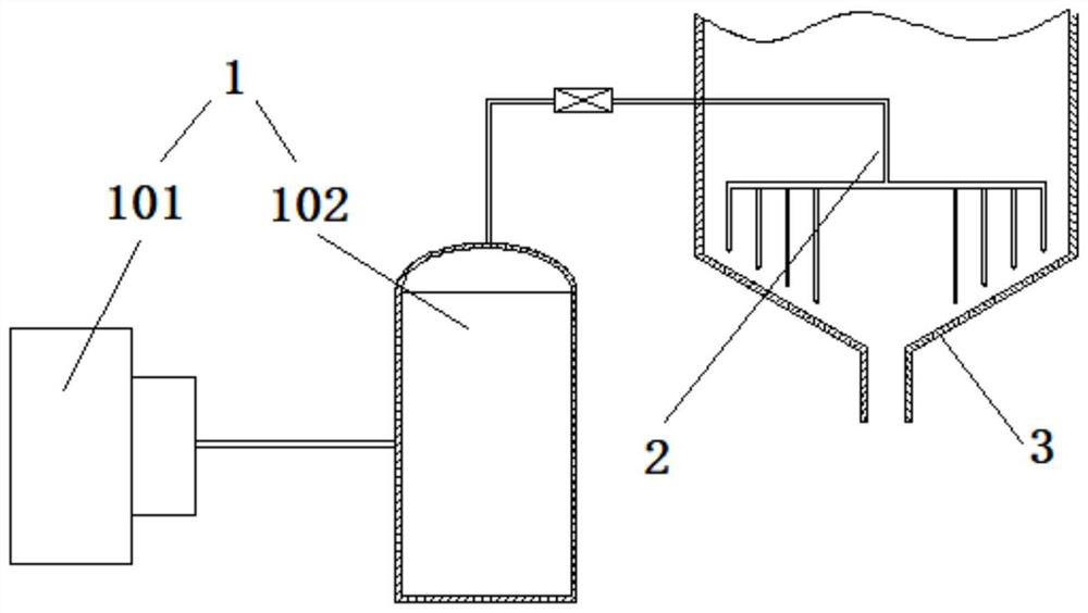
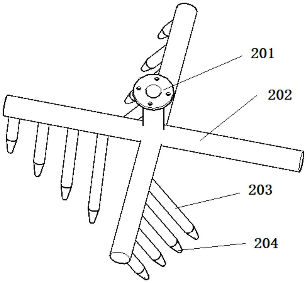
[0019]Please refer tofigure 1 withfigure 2,figure 1 Is a general schematic view of the present invention,figure 2It is a schematic structural diagram of the dispenser of the present invention. A wet desulfurization process uses a displaced device, including a gas source system 1 and a dispenser 2, a gas source system for intermittently supplying a compressed gas, a sulfur on the wall surface of the container 3, and a liquid.

[0020]The gas source system 1 includes a compressor 101 and a gas storage tank 102 sequentially connected, and the compressor is used to boost the gas, and the gas storage tank is used to store high-pressure gas for dispense use. A valve is provided on the gas outlet line on the top of the gas tank, preferably an electromagnetic valve or the like for quick opening, and off. After the valve is opened, the dispenser can supply compressed gas; the valve is turned off and the compressor can store the high pressure gas.

[0021]The dispenser 2 is located within the conta...


PUM


Abstract

The invention discloses a blockage removing device for a wet desulphurization process. The blockage removing device comprises a distributor and a gas source system, wherein the distributor comprises a central pipe and a plurality of branch pipes, the central pipe is used for supplying air to the branch pipes, one end of each branch pipe is communicated with the central pipe, the other ends of the branch pipes are radially arranged in a star shape around the central axis of the central pipe, each branch pipe is provided with a nozzle, the nozzle faces downwards, an included angle between the nozzle and the central axis of the central pipe is an acute angle, and the gas outlet of the gas source system is communicated with the central pipe and used for intermittently providing compressed gas for the distributor. According to the invention, a fluid intermittently impacts sulfur blocks on the wall surface of a container while a desulfurization liquid rotates to form stirring and scouring, so that sulfur can be well prevented from caking on the wall surface of the container, the caked sulfur can be well impacted and crushed, and can be prevented from being agglomerated into large blocks, the good capacity of cleaning the sulfur on the wall surface of the container is achieved, shutdown caused by blockage of the container due to settlement is avoided, and long-period operation of the device is facilitated.

Description

Technical field[0001]The present invention relates to the field of crane attachments, in particular, a wet desulfurization process is interpolated.Background technique[0002]With a large number of oil fields in the oil field, there is often a single sulfur precipitation, blockage the tower and pipeline during operation of the wet desulfurization device, and currently reduce the amount of settlement by optimizing the desulfurization agent parameters, and can effectively reduce the plugging frequency. In addition, the optimization pipe size, increase dredging equipment, etc., it is also possible to treat sulfur blockage in the pipeline, but the desulfurization liquid flows slowly in containers such as tower, tank, and kettle, and sulfur particles are very contained in the head. Cake and ultimately lead to blockage, once clogging requires a shutdown and maintenance, for example, the demolished and clogged container enters its internal cleaning, so that the workload is large and not cond...

Claims


Application Information

Patent Timeline
Patent Type & Authority Applications(China)
IPC IPC(8): B01D53/78B01D53/86B02C19/06
CPCB01D53/78B01D53/8603B02C19/06
Inventor 黄前名王建军郭伟
Owner 四川恒乐达能源工程有限公司
Learn More