
A firing safety mechanism of a cutting stapler

A firing insurance and stapler technology, applied in the field of medical staplers, can solve problems such as poor suture, inability to inductively lock, and unfavorable tissue rapid cutting and suture, so as to prevent tissue damage, improve suture cutting efficiency, and avoid poor suture conditions. Effect

Active Publication Date: 2021-11-19
PEOPLES HOSPITAL OF ZHENGZHOU
View PDF11 Cites 0 Cited by
  • Summary
  • Abstract
  • Description
  • Claims
  • Application Information

AI Technical Summary

Problems solved by technology

[0003] However, the anti-secondary firing safety mechanism of the above-mentioned linear cutting stapler still has obvious defects during use: 1. After the above-mentioned device clamps the tissue, it prevents misoperation through the safety mechanism provided by itself, but the safety mechanism It needs to be released manually, and after the clipping is completed, the safety hook needs to be disengaged manually, which is not conducive to the rapid cutting and suturing of tissues; 2. The above-mentioned device cannot evaluate the tissue that needs to be sutured, because the stapler has the optimal suturing width, which is lower than the optimal suturing width. When the optimal suturing width or the width of the tissue to be sutured is too large, it may lead to poor suturing, and the stapler of the prior art usually requires the physician to judge by himself. Unable to perform inductive locking; 3. The stapler in the prior art is similar to a splint structure, and the force is relatively strong during the clamping process, which is easy to damage the tissue

Method used


Image

  • A firing safety mechanism of a cutting stapler
  • A firing safety mechanism of a cutting stapler
  • A firing safety mechanism of a cutting stapler

Examples


Embodiment

[0029] see Figure 1-10 , the present invention provides a technical solution:

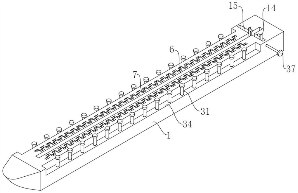
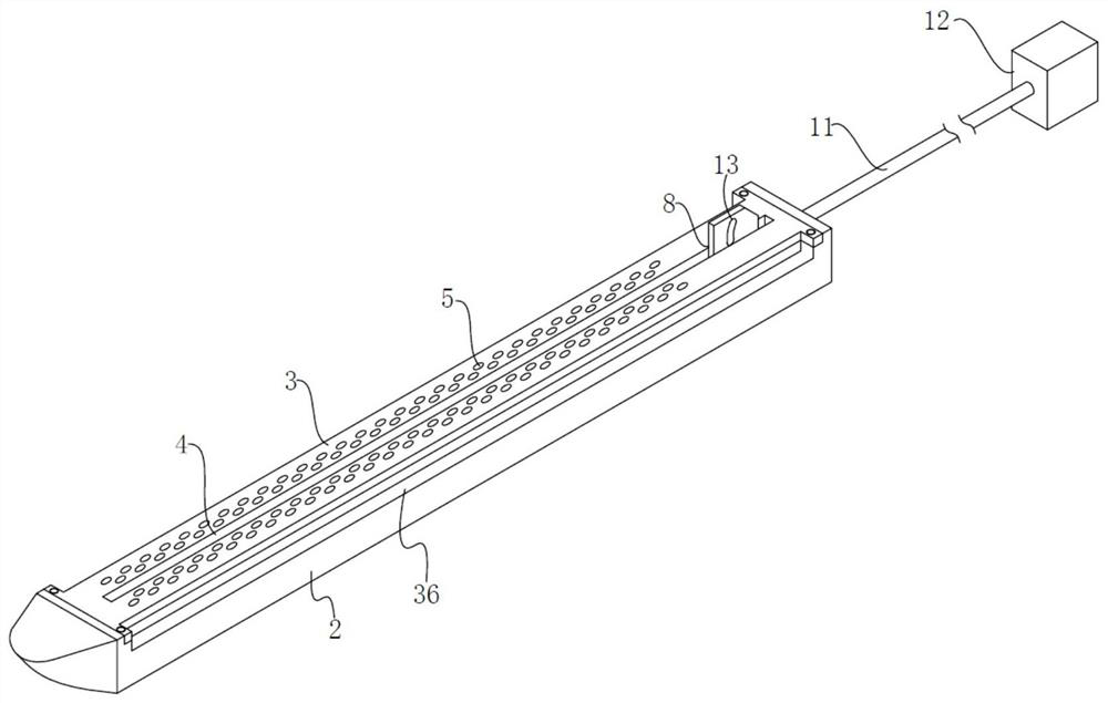
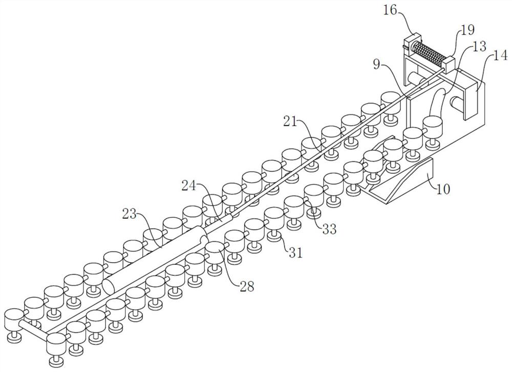
[0030] A firing safety mechanism for a cutting stapler, comprising a nail abutment seat 1 and a nail capsule seat 2, the nail abutment seat 1 and the nail capsule seat 2 are set up and down correspondingly, a nail capsule 3 is fixedly installed on the nail capsule seat 2, and the middle part of the nail capsule 3 Cutting slots 4 are provided, nail outlet holes 5 are arranged in an array on the nail bays 3 on both sides of the cutting slots 4, and the middle part of the anvil seat 1 is provided with cutting matching slots 6 corresponding to the cutting slots 4, and the cutting matching slots 6 are arrayed on both sides. There are nail abutting grooves 7 corresponding to the nail outlet holes 5 one by one;

[0031] The tissue to be cut and sutured is clamped by the upper and lower closure of the nail anvil 1 and the nail cabin 2, and then it is sutured and cut. The used nail cabin 3 can be removed ...


PUM


Abstract

The invention provides a firing safety mechanism of a cutting stapler, a firing device and a stapler thereof, including a nail abutment seat and a nail cabin seat, the nail abutment seat and the nail cabin seat are set up and down correspondingly, and the nail cabin seat is fixedly installed There is a nail cabin, a cutting groove is opened in the middle of the nail cabin, the fixed seat is fixedly installed at the bottom of the limit chute, and the traction rope is set on several direction-changing gears, and the direction-changing gears are movably installed on the arrival The traction hydraulic cylinder in the nail seat is fixedly installed in the nail abutment seat, and the end of the return spring away from the piston is fixedly connected to the inner wall of the cylinder. The invention is provided with an induction hydraulic cylinder group, which can automatically perform insurance without any additional operation. Unlocking and locking, at the same time, it can sense the width of the tissue to be sutured, effectively avoiding poor suturing when the sutured tissue is too wide or too narrow, and can also generate a stable supporting force during the closing process of the anvil seat and the nail cabin seat, preventing the abutment The tissue damage caused by the rapid closure of the nail seat and the nail cabin seat ensures the safety of the anastomotic process.

Description

technical field [0001] The invention relates to the technical field of medical staplers, in particular to a firing safety mechanism of a cutting stapler. Background technique [0002] In the prior art, the application number is "CN201721636418.7", a linear cutting stapler with a firing safety function, including a handle, a component splint, a firing component, a nail pushing plate and a staple cartridge; one end of the component splint is set in the handle; The firing assembly is slidably connected with the splint of the assembly, and pushes the nail pushing plate to extend into the nail bin; the firing assembly includes a slider; it also includes a safety mechanism; the safety mechanism includes a limit assembly and a switch assembly; to the installation slot on the rear end face; the side wall of the component splint is provided with a limit through hole; the limit component is installed in the installation groove, and cooperates with the limit through hole when the firin...

Claims


Application Information

Patent Timeline
Patent Type & Authority Patents(China)
IPC IPC(8): A61B17/072
CPCA61B17/07207A61B2017/00367A61B2017/07214
Inventor 王红山徐靖文
Owner PEOPLES HOSPITAL OF ZHENGZHOU
Learn More