Transformer substation high-tension lightning arrester leakage current abnormity alarm device
A leakage current and abnormal alarm technology, applied in measuring devices, only measuring current, measuring current/voltage, etc., can solve problems such as affecting the use of leakage ammeter, no obvious alarm device, and easy to miss hidden troubles, so as to improve the inspection efficiency. and quality, easy to control the state of the equipment, the effect of not easy to move the position
- Summary
- Abstract
- Description
- Claims
- Application Information
AI Technical Summary
Problems solved by technology
Method used
Image

Examples
Embodiment 1
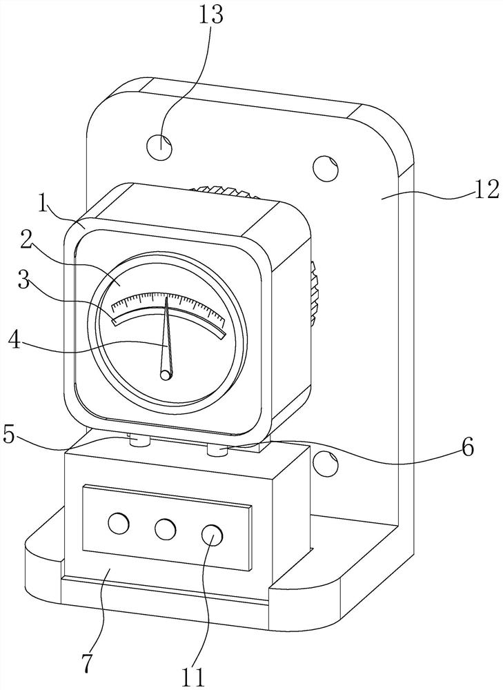
[0026] Such as Figure 1-6 As shown, the present invention provides a technical solution: a substation high-voltage arrester leakage current abnormal alarm device, including a leakage current meter 1 and a mounting plate 12, the front of the leakage current meter 1 is fixedly installed with a dial 2, and the inside of the dial 2 is fixedly installed with a sliding The rheostat 3 is provided with a scale inside the dial 2, and the scale and the sliding rheostat 3 are arranged in an arc shape, the sliding rheostat 3 is installed on the lower part of the scale, and the inside of the dial 2 is equipped with a pointer 4, The pointer 4 is a sliding vane type, and the bottom end of the leakage ammeter 1 is fixedly installed with the first connecting column 5, and the end of the leakage ammeter 1 far away from the first connecting column 5 is fixedly installed with the second connecting column 6, and the bottom of the leakage ammeter 1 is fixedly installed Device box 7 is arranged, an...
Embodiment 2
[0029] Such as Figure 1-6 As shown, on the basis of the first embodiment, the present invention provides a technical solution: an installation hole 13 is opened inside the installation plate 12 , and an installation groove 14 is opened at the bottom of the installation plate 12 .
[0030] In this embodiment, by setting the installation hole 13, by inserting the bolt inside the installation hole 13, the installable plate 12 can be fixed in the installation column of the lightning arrester, and by setting the installation groove 14, the bottom of the device box 7 is located in the installation groove 14 , the installation of the device box 7 and the leakage ammeter 1 is conducive to the installation of the device box 7 and the leakage ammeter 1.
Embodiment 3
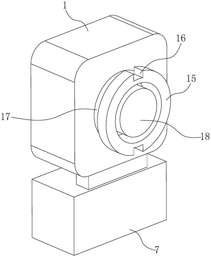
[0032] Such as Figure 1-6 As shown, on the basis of Embodiment 1 and Embodiment 2, the present invention provides a technical solution: a central cylinder 18 is fixedly installed on the back of the leakage ammeter 1, a cavity 26 is opened inside the locking disc 21, and the central cylinder 18 and The specifications and dimensions of the cavity 26 are suitable.
[0033] In this embodiment, when the leakage ammeter 1 is installed, the central barrel 18 is put into the cavity 26 , which is beneficial to the connection between the leakage ammeter 1 and the locking plate 21 , thereby facilitating the installation of the leakage ammeter 1 .
PUM
 Abstract
Description
Claims
Application Information
 - Generate Ideas
- Intellectual Property
- Life Sciences
- Materials
- Tech Scout
- Unparalleled Data Quality
- Higher Quality Content
- 60% Fewer Hallucinations
Browse by: Latest US Patents, China's latest patents, Technical Efficacy Thesaurus, Application Domain, Technology Topic, Popular Technical Reports.
© 2025 PatSnap. All rights reserved.Legal|Privacy policy|Modern Slavery Act Transparency Statement|Sitemap|About US| Contact US: help@patsnap.com