
S2 flow field diagnosis method based on inter-stage measurement parameters of axial flow compressor

An axial-flow compressor, a technology for measuring parameters, applied in gas turbine devices, mechanical equipment, jet propulsion devices, etc., can solve the problems of multi-stage compressor matching damage, accumulated errors, and deviation of calculation results.

Active Publication Date: 2021-04-02
BEIHANG UNIV
View PDF22 Cites 2 Cited by
  • Summary
  • Abstract
  • Description
  • Claims
  • Application Information

AI Technical Summary

Problems solved by technology

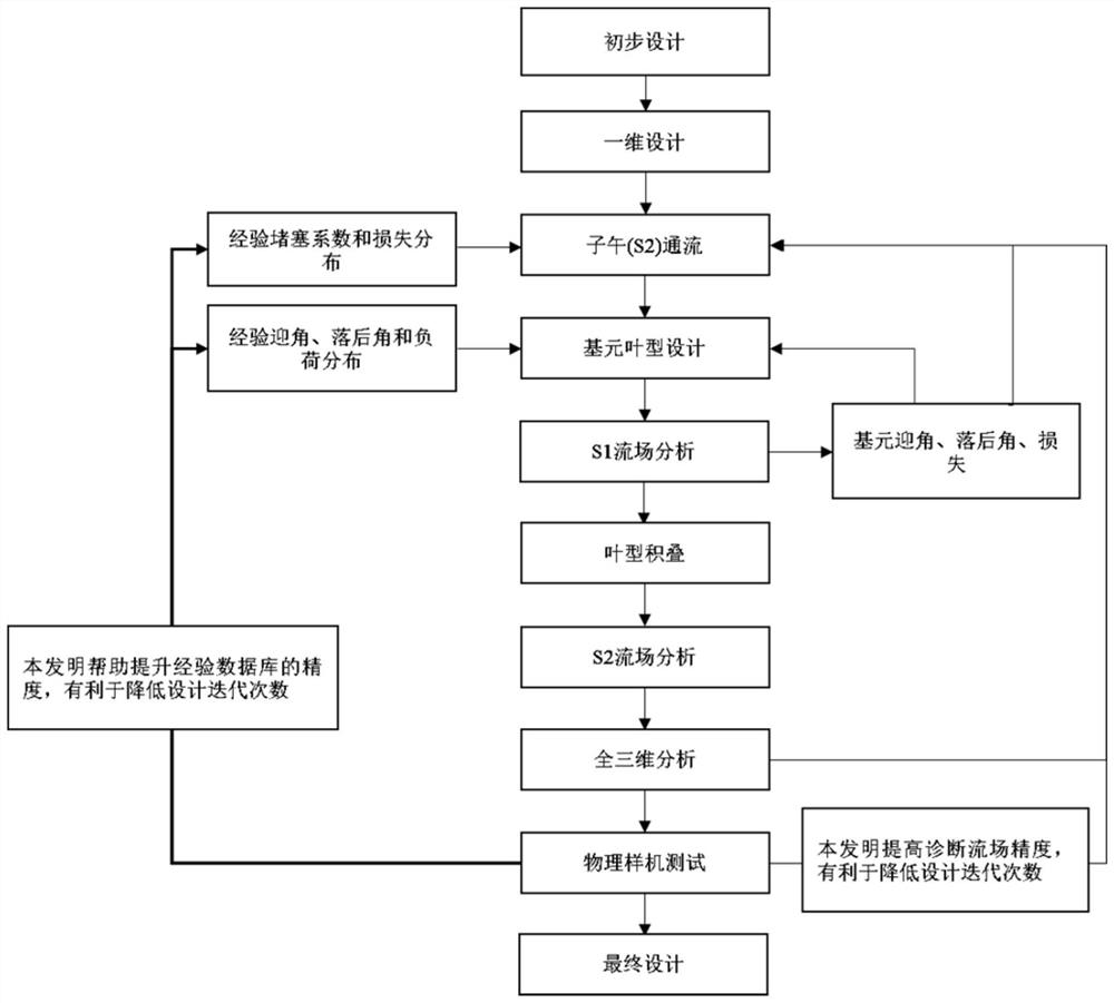
However, the static-rotary interface acts as a mixing surface, which homogenizes the non-uniform flow at the outlet of the front blades, artificially adds mixing, and generates additional entropy increase
At the same time, the leakage flow, disk cavity flow, geometric shape and other parameters in the multi-stage compressor may have large differences between CFD and the real physical prototype
Then the error generated by this processing method may not be very large when the number of stages is small, but once the number of stages increases, the calculation results of the subsequent stages will deviate, and the matching of multi-stage compressors will be destroyed. The more stages, the more cumulative error

Method used


Image

  • S2 flow field diagnosis method based on inter-stage measurement parameters of axial flow compressor
  • S2 flow field diagnosis method based on inter-stage measurement parameters of axial flow compressor
  • S2 flow field diagnosis method based on inter-stage measurement parameters of axial flow compressor

Examples


example

[0212] Example description:

[0213] Based on the present invention, a S2 flow field diagnosis method based on the interstage measurement parameters of the axial flow compressor is proposed, and the application of this method in the S2 flow field diagnosis process of the multistage compressor is initially explored, and the feasibility of the present invention is verified by comparative analysis sex.

[0214] In view of the dimensionality reduction characteristics and model selection brought about by the governing equations, the key technologies and difficulties can be summarized as follows:

[0215] 1) In the compressor prototype test, it is very likely to work at a non-design point

[0216] Under such working conditions, there may be obvious flow separation, and the angle of attack seriously deviates from the design working point. Its flow field may deviate greatly from the design conditions, and in severe cases, meridian backflow may occur. To solve this difficulty, in th...


PUM


Abstract

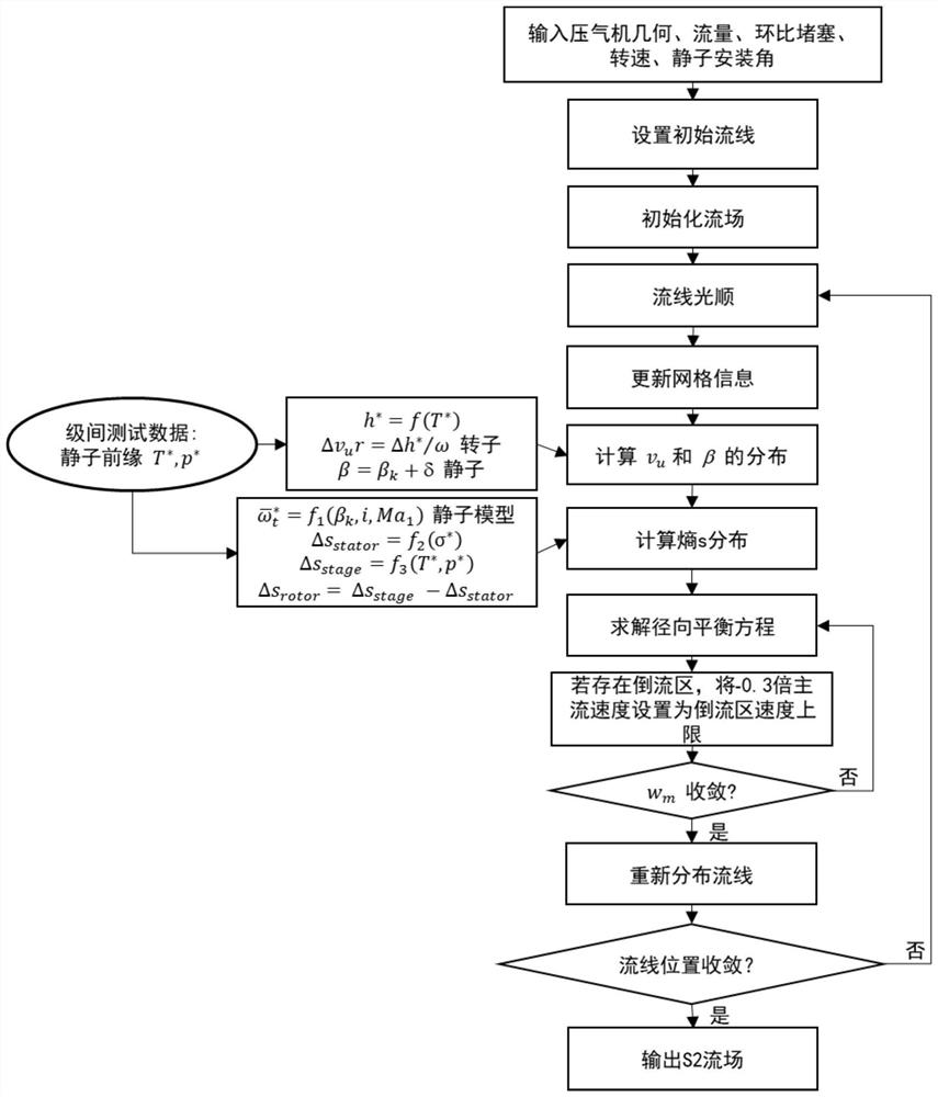
The invention discloses an S2 flow field diagnosis method based on inter-stage measurement parameters of an axial flow compressor. The S2 flow field diagnosis method specifically comprises the steps of 1, establishing a corresponding S2 flow field calculation streamline curvature control equation according to the inter-stage measurement parameters of the multi-stage axial flow compressor; 2, according to the fact that the possible total temperature rise of the multi-stage compressor is high, considering the influence of inter-stage measurement parameters by adopting a variable specific heat working medium; 3, obtaining stator lag angle and entropy distribution parameters in the flow field according to a thermodynamic relationship and a stator model; 4, performing flow field calculation toobtain an axial flow compressor S2 flow field inversion result according to the inter-stage measurement parameters; and 5, performing analysis and diagnosis according to calculation results such as flow field parameters and performance parameters obtained by inversion. According to the method, the variable specific heat working medium is adopted, and the accuracy is higher when the conditions thatthe stage number of the compressor is large and the temperature rise is large are treated; and the assumption that the static pressure of measuring points at different heights is equal to the wall surface static pressure in the multi-stage compressor test is broken through, the flow field result automatically meets the radial balance equation, the S2 flow field diagnosis precision is higher, andthe compressor design cycle is reduced.

Description

technical field [0001] The invention relates to an S2 flow field diagnosis method based on interstage measurement parameters of an axial flow compressor, which relates to aerodynamics and aerodynamic gas turbine engine compressor test flow field diagnosis, and belongs to the field of aerodynamic design analysis of aerogas turbine engine compressors . Background technique [0002] The aero engine is the power source of the aircraft, so the improvement of the performance of the aircraft requires the engine of the aircraft to be strong enough. Foreign advanced engines can now reach a thrust-to-weight ratio of 10, and the temperature before the turbine is 2000K. The use of high-thrust-to-weight ratio and high-thrust engines has greatly improved the performance of the aircraft, so the requirements for engine performance are also rising. Our country is striving to shorten the gap with advanced foreign countries. [0003] The traditional design process of the engine, no matter t...

Claims


Application Information

Patent Timeline
IPC IPC(8): F02C3/06F02C7/00F04D27/00
CPCF02C3/06F02C7/00F04D27/001
Inventor 金东海桂幸民周成华
Owner BEIHANG UNIV
Learn More