Rapid installation equipment for lifeline stand column

A technology for installing equipment and lifelines, applied in the processing of building materials, construction, building structure, etc., can solve the problems of large limitations of lifeline columns, low assembly efficiency, multiple labor costs, etc., to improve installation efficiency and ensure safety. , to ensure the effect of stability

Active Publication Date: 2021-04-02
CHINA CONSTR FOURTH ENG DIV INSTALLATION ENG
View PDF5 Cites 1 Cited by
  • Summary
  • Abstract
  • Description
  • Claims
  • Application Information

AI Technical Summary

Problems solved by technology

[0002] In the process of building steel structure construction, in order to ensure the safety of workers working at heights, it is necessary to install lifeline protection on the steel beam. The traditional method is to weld the connecting plate on the steel beam, and then install the lifeline column on the connecting plate with clamps. or directly weld the lifeline column to the steel beam. However, when the lifeline column is installed and removed, it will cause certain damage, and even after the damage, it will be polished and repainted, resulting in more labor costs.
[0003] The existing installation of lifeline columns is done manually. The efficiency of assembly is not only low, but also requires skilled employees to effectively ensure the strength of the columns, which makes the limitations of lifeline columns larger. Nowadays, There is no equipment that can quickly install the lifeline column. Therefore, a device that can automatically install the lifeline column is designed to improve the installation efficiency of the lifeline column.

Method used


Image

  • Rapid installation equipment for lifeline stand column
  • Rapid installation equipment for lifeline stand column
  • Rapid installation equipment for lifeline stand column

Examples


Embodiment

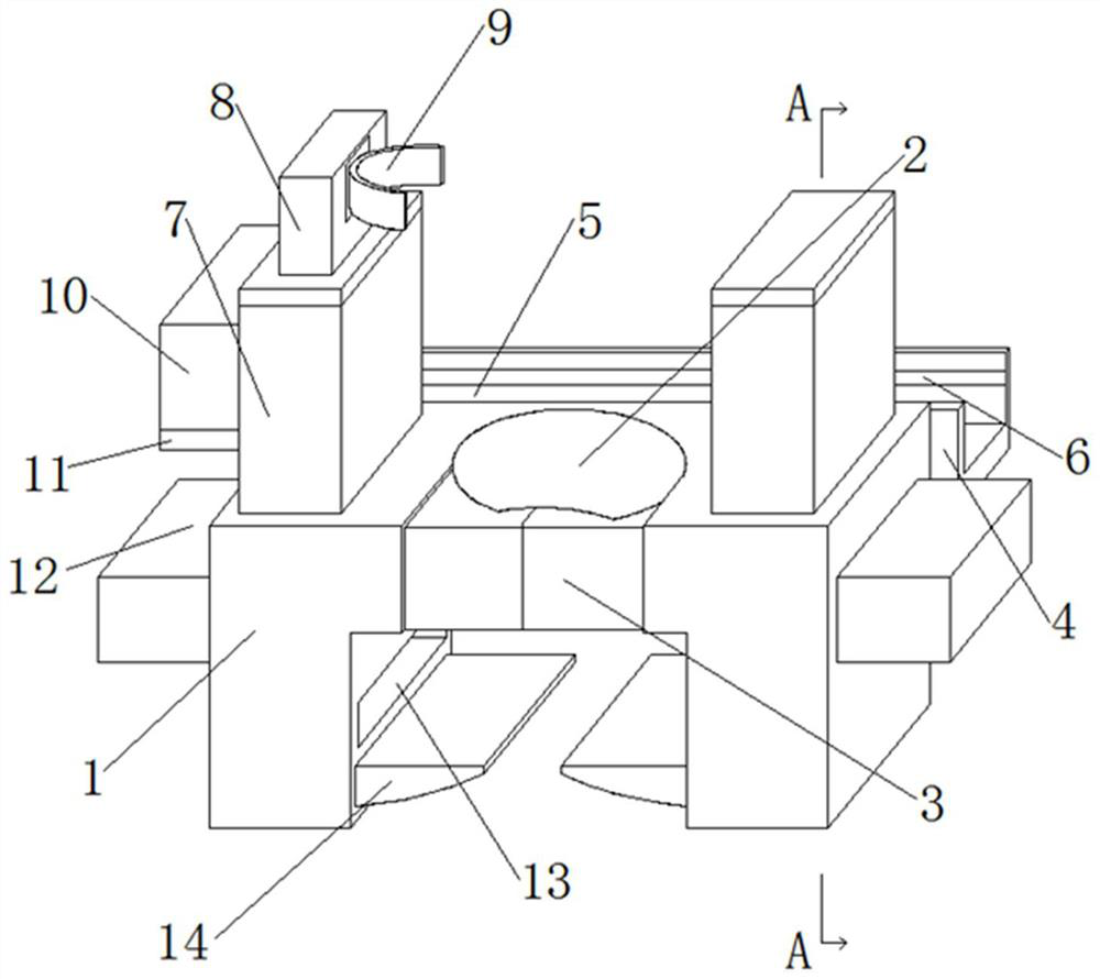
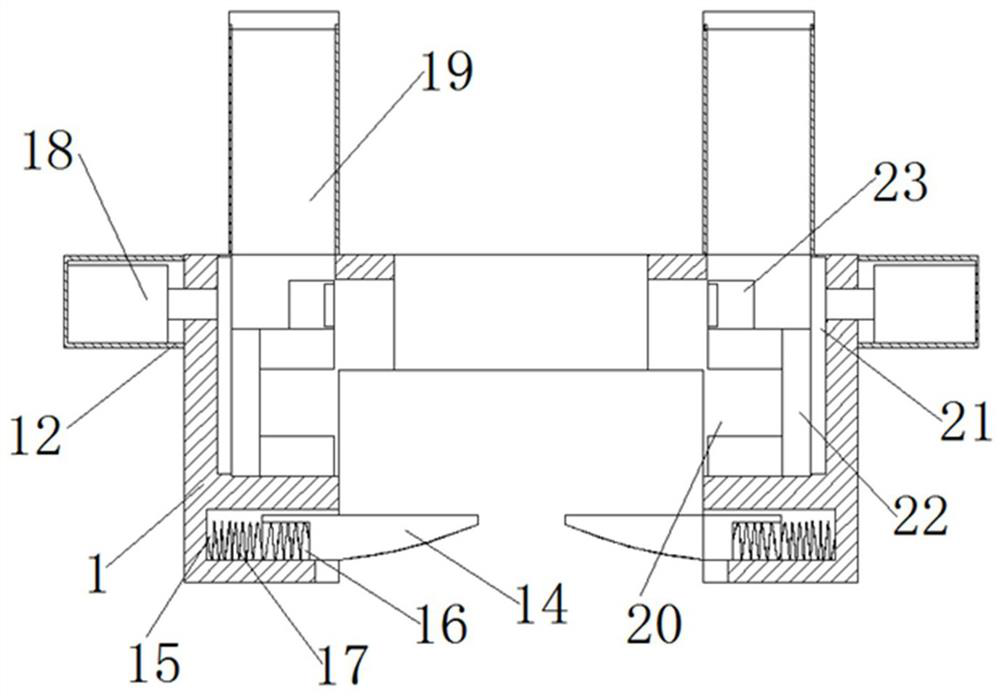
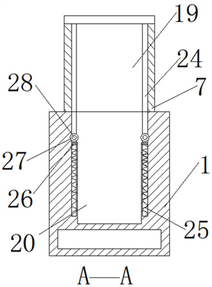
[0030] Such as Figure 1-6As shown, a quick installation device for a lifeline column includes a device body 1, the device body 1 is arranged on a steel beam 38, a jack 2 is arranged on the device body 1, and a movable block 3 is arranged on one side of the jack 2 The two sides of the jack 2 are provided with a placement box 7, and one side of the placement box 7 is provided with a control box 10, and the bottom of the control box 10 is provided with a storage battery 11, and the inside of the device body 1 is provided with a movable chamber 20. Both sides are provided with draw-in groove 24, and the bottom of draw-in groove 24 is provided with second spring 25, and the top of second spring 25 is provided with support plate 26, and bolt 28 is placed on support plate 26, several groups of bolts 28 are placed on support plate 26, after the uppermost bolt 28 is installed, through the elasticity of the second spring 25, the lower bolt 28 can be overlapped with the position before ...


PUM


Abstract

The invention relates to rapid installation equipment for a lifeline stand column. The rapid installation equipment comprises a device body, a movable cavity is formed in the device body, clamping grooves are formed in the two sides of the movable cavity, a movable block is arranged on one side of each clamping groove, a third spring is arranged on one side of each movable block, a vertical plateis arranged at the other end of each third spring, the vertical plates are arranged above a movable plate, a fourth spring is arranged below the movable plate, and the fourth spring is arranged in a vertical groove formed in the device body. The rapid installation equipment has the beneficial effects that the situation that installation of the lifeline stand column is affected due to the fact thatthe number is insufficient or in the using process, parts are prone to falling off can be effectively avoided, installation is more convenient, danger generated in the installation process is reduced, safety in the installation process is guaranteed, when a clamping piece is fixed, the fastening degree of a protection plate can be determined through the rotating time of a rotating disc, and thenrapid assembling can be conducted.

Description

technical field [0001] The invention relates to a quick installation device for a lifeline column, and belongs to the technical field of high-altitude operation safety protection equipment. Background technique [0002] In the process of building steel structure construction, in order to ensure the safety of workers working at heights, it is necessary to install lifeline protection on the steel beam. The traditional method is to weld the connecting plate on the steel beam, and then install the lifeline column on the connecting plate with clamps. or directly weld the lifeline column to the steel beam. However, when the lifeline column is installed and removed, it will cause certain damage, and even after the damage, it will be polished and repainted, resulting in more labor costs. [0003] The existing installation of lifeline columns is done manually. The efficiency of assembly is not only low, but also requires skilled employees to effectively ensure the strength of the col...

Claims


Application Information

Patent Timeline
Patent Type & Authority Applications(China)
IPC IPC(8): E04G21/32
CPCE04G21/3261
Inventor 吴家雄孙晗刘虹陆文杰李斯麟
Owner CHINA CONSTR FOURTH ENG DIV INSTALLATION ENG
Why Eureka
Try Eureka