Eureka AIR delivers breakthrough ideas for toughest innovation challenges, trusted by R&D personnel around the world.

Automatic snow shoveling and loading device

An automatic and compacting device technology, applied in the engineering field, which can solve the problems of single function and inability to remove the ice surface.

Inactive Publication Date: 2021-04-02
王辰
View PDF13 Cites 0 Cited by
  • Summary
  • Abstract
  • Description
  • Claims
  • Application Information

AI Technical Summary

Problems solved by technology

[0002] Snow plowing device is a common construction machinery, but the general snow plowing device is manually operated, the ice surface cannot be shoveled clean, and the function is relatively single

Method used


Image

  • Automatic snow shoveling and loading device
  • Automatic snow shoveling and loading device
  • Automatic snow shoveling and loading device

Examples


specific Embodiment approach 1

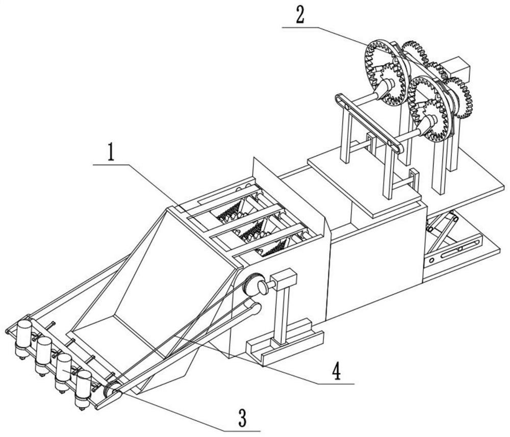
[0028] Combine below Figure 1-12 Description of this embodiment, an automatic snow plowing and loading device, including a snow collection device 1; a compaction device 2; an ice breaking device 3; a belt 4, the snow collection device 1 is connected with the compaction device 2, 1 is connected with the ice breaking device 3 through the belt 4.

specific Embodiment approach 2

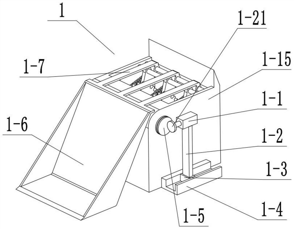
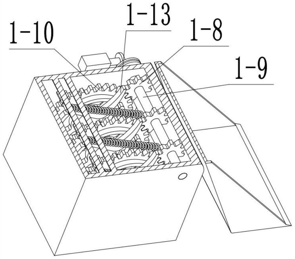
[0030] Combine below Figure 1-12Describe this embodiment, this embodiment will further explain Embodiment 1, the snow harvesting device 1 includes a motor 1-1; a support rod 1-2; a slider 1-3; a chute 1-4; One 1-5; snow bucket 1-6; support rod two 1-7; gear one 1-8; fixed rod one 1-9; gear two 1-10; bump one 1-11; bump two 1- 12; power hook 1-13; fixed rod two 1-14; shell 1-15; fixed rod three 1-16; fixed rod four 1-17; tension spring 1-18; fixed column 1-19; fixed rod five 1 -20; Runner two 1-21, motor 1-1 is fixedly connected with support rod one 1-2, support rod one 1-2 is fixedly connected with slide block 1-3, slide block 1-3 is slidably connected in chute 1 On -4, the chute 1-4 is fixedly connected with the shell 1-15, the motor 1-1 is fixedly connected with the second runner 1-21, the first runner 1-5 is connected with the second runner 1-21, and three supports Rod two 1-7 are all fixedly connected with snow bucket 1-6, three gears one 1-8 are all fixedly connected w...

specific Embodiment approach 3

[0033] Combine below Figure 1-12 Describe this embodiment, this embodiment will further explain the first embodiment, the compacting device 2 includes motor two 2-1; gear three 2-2; gear four 2-3; connecting rod one 2-4; One 2-5; connecting frame 2-6; connecting rod two 2-7; hinged column one 2-8; gear five 2-9; internal gear 2-10; bracing frame 2-11; hinged column two 2-12; Connecting rod three 2-13; Small cylinder one 2-14; Transverse groove 2-15; Support rod two 2-16; Small cylinder two 2-17; Vertical groove 2-18; Compacting plate 2-19; 2-20; Support rod three 2-21; Support rod four 2-22, upper bearing plate 2-23; Upper notch 2-24; Upper hinged column one 2-25; Upper hinged column two 2-26; Connecting rod Four 2-27; Connecting rod five 2-28; Connecting rod six 2-29; Connecting rod seven 2-30; ; Lower hinge column one 2-35; Lower hinge column two 2-36; Pressure bar one 2-37; Pressure bar two 2-38, motor 2-1 is fixedly connected with gear three 2-2, two gears four 2- 3 ar...


PUM


Abstract

The invention relates to the field of engineering, in particular to an automatic snow shoveling and loading device. The functions of automatic snow collecting and truck loading can be achieved, the ice shaving function can be achieved, the position of the motor is changed, and the ice shaving and truck loading speed can be adjusted; and the automatic compaction height can be adjusted by adjustingthe height of the lifter. The device comprises a snow collecting device; a compaction device; an icebreaking device; and a belt which changes the rotating speed of the first rotating wheel, so that the snow collecting speed is changed, the snow collecting speed can be increased on the road surface with much blood and snow, the snow collecting speed can be decreased on the road surface with littlesnow, energy is saved, and variability is improved. The initial position of the compaction plate is changed, so that the snow compaction effect is changed; the rotating speed of the rotating wheel IIIis changed, so that the rotating speed of the functional rod is changed, the movement speed of the ice breaking head is changed, the ice breaking and snow hardening speed is changed, the speed can beincreased on a road with more ice, the speed can be reduced on a road with less ice, energy is saved, and variability is improved.

Description

technical field [0001] The invention relates to an engineering field, in particular to an automatic snow removal and loading device. Background technique [0002] Snow removal device is a common construction machinery, but the general snow removal device is manually operated, the ice surface cannot be removed cleanly, and the function is relatively single. Contents of the invention [0003] The purpose of this invention is to provide a common construction machine, which can automatically collect snow and load the car, and can also shave ice, change the position of the motor, and can adjust the speed of shaving ice and loading; adjusting the height of the lifter can adjust the automatic compaction the height of. [0004] The purpose of the present invention is achieved through the following technical solutions: [0005] An automatic snow plowing and loading device, comprising a snow collecting device; a compacting device; an ice breaking device; a belt, the snow collectin...

Claims


Application Information

Patent Timeline
Patent Type & Authority Applications(China)
IPC IPC(8): E01H5/12
CPCE01H5/12
Inventor 王辰
Owner 王辰
Why Eureka
Eureka Blog
Learn More