
Rotary staggered discharging structure and tableware taking device thereof

A rotary tableware technology, applied in the field of mechanical equipment, can solve the problems of increasing the weight of the tableware taker, many procedures, unreliable whereabouts, etc.

Pending Publication Date: 2021-04-02
KOLOR MAGNETICSHENZHENCO LTD
View PDF0 Cites 1 Cited by
  • Summary
  • Abstract
  • Description
  • Claims
  • Application Information

AI Technical Summary

Problems solved by technology

However, because the larger volume of the pendulum block will increase the weight of the tableware remover, it is more difficult to move, and sometimes the pusher pushes the tableware at the bottom of the silo and the tableware cannot completely deviate from the supporting block and fall. The whereabouts are unreliable. Sometimes the tableware will still be stuck in the bin. At this time, it is necessary to take out all the tableware in the bin and stack them in the bin one by one. Unloading again, this is a lot of procedures and troublesome, which greatly affects the meal time

Method used


Image

  • Rotary staggered discharging structure and tableware taking device thereof
  • Rotary staggered discharging structure and tableware taking device thereof
  • Rotary staggered discharging structure and tableware taking device thereof

Examples


Embodiment Construction

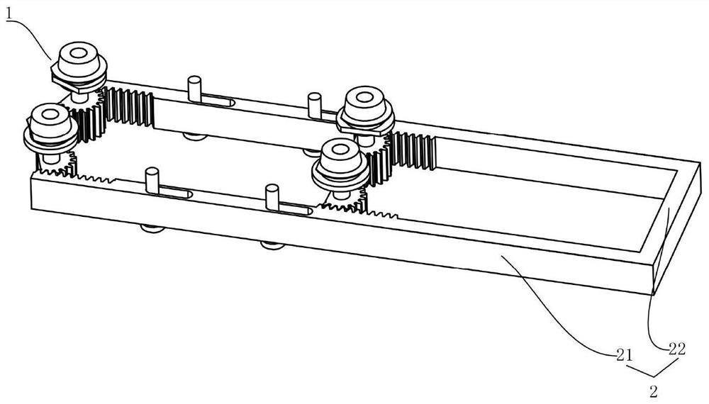
[0034] The present invention will be described in further detail below in conjunction with accompanying drawing, and these accompanying drawings are all simplified schematic diagrams, only illustrate the basic structure of the present invention in a schematic way, and the direction of this specific implementation is based on figure 1 Orientation is standard.

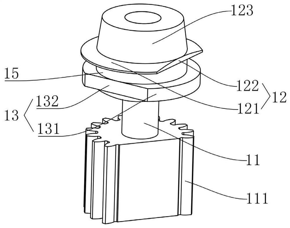
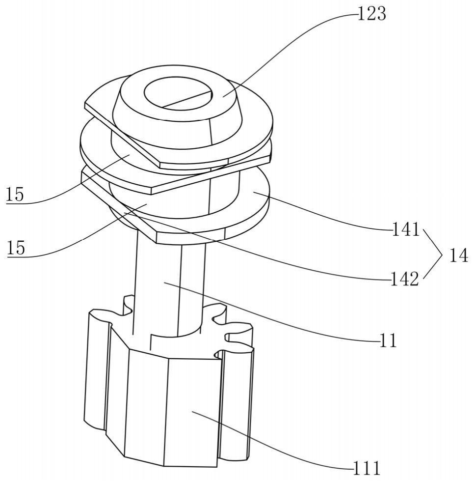
[0035] Such as figure 1 , figure 2 As shown, a rotary dislocation blanking structure includes a supporting block 1 and a driving member 2. The supporting block 1 includes a rotating shaft 11, a first supporting piece 12, a second supporting piece 13, a first supporting piece 12, a second supporting piece Sheets 13 are sequentially stacked on the rotating shaft 11, the first supporting sheet 12 includes a first supporting portion 121 for supporting materials and a first blanking portion 122 for discharging materials, and the second supporting sheet 13 includes a first supporting portion 122 for supporting materials. Th...


PUM


Abstract

The invention relates to the field of mechanical equipment, in particular to a rotary staggered discharging structure and a tableware taking device thereof. The supporting block of the rotary staggered discharging structure comprises a rotating shaft, a first supporting piece and a second supporting piece, the first supporting piece and the second supporting piece are sequentially stacked on the rotating shaft, and the first supporting piece comprises a first bearing part used for supporting materials and a first discharging part used for discharging; the second supporting piece comprises a second bearing part used for supporting materials and a second discharging part used for discharging, the first discharging part and the second discharging part are arranged in an up-down staggered mode, one end of the rotating shaft is in transmission connection with the driving piece, and the supporting block is driven by the driving piece to rotate for discharging. According to the invention, thedriving piece drives the supporting block for supporting tableware to discharge, the supporting block rotates by a staggered angle, so that the tableware on the lower layer loses the supporting platform, the tableware does not need to move left and right or move front and back to be discharged, two different discharging modes are adopted compared with the mode that the tableware is linearly pushed to move by a certain distance and then disengaged from the platform, and the rotary staggered discharging structure is simpler, more elegant, smaller in size adjustability and lighter in weight correspondingly.

Description

technical field [0001] The invention relates to the field of mechanical equipment, more specifically, to a rotary dislocation feeding structure and a tableware taker. Background technique [0002] Along with the development of catering industry, a kind of tableware taker has appeared on the market. The tableware taker is equipped with a bracket for supporting the tableware and an inclined chute for guiding the falling tableware. The unloading of the tableware taker is by setting a pendulum block at the end of the inclined chute, and at the bottom of the silo. A push piece is set next to the tableware, one end of the pendulum block is connected with the push piece, and the other end of the pendulum block is connected with the fallen tableware. When the fallen tableware is pulled, the pendulum block will be dragged, thereby driving the push piece to move the The lowest level of cutlery was pushed down. However, because the larger volume of the pendulum block will increase th...

Claims


Application Information

Patent Timeline
IPC IPC(8): A47G21/00
CPCA47G21/00A47F1/10A47F2001/103
Inventor 李清茂李志伟
Owner KOLOR MAGNETICSHENZHENCO LTD
Learn More