Concrete drilling and coring machine for constructional engineering quality supervision
A technology of quality supervision and drilling and coring, which is applied in the field of construction engineering, can solve the problems of high dust in coring operations, inconvenient drilling samples, etc., and achieve the effects of improving efficiency, shortening sampling time, and safe working environment
- Summary
- Abstract
- Description
- Claims
- Application Information
AI Technical Summary
Problems solved by technology
Method used
Image

Examples
Embodiment 1
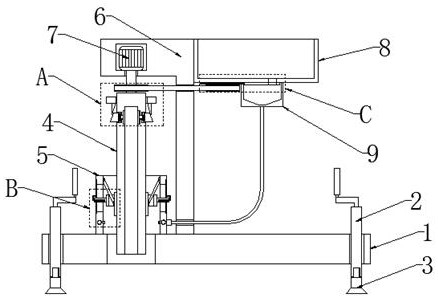
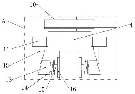
[0029] refer to figure 1 and figure 2 , a concrete drilling and coring machine for quality supervision of construction projects, comprising a bottom plate 1, threaded rods 2 distributed vertically through the four corners of the bottom plate 1, and a support is installed on the bottom end of the threaded rod 2 Leg 3, the top of threaded rod 2 is fixedly connected with handle, and the top of base plate 1 is fixedly connected with installation frame 6, and installation frame 6 is automatic retractable setting, and the inside of installation frame 6 is fixedly installed with drive motor 7, and the drive motor 7 The end of the output shaft is fixed with a drill bit 4 by screws, the drill bit 4 is provided with an auxiliary sampling device, the peripheral side wall of the output shaft of the driving motor 7 is fixedly sleeved with a main pulley 10, and the side wall of the mounting frame 6 is fixedly equipped with a water tank 8 , and the bottom of the water tank 8 is fixedly con...
Embodiment 2
[0033] refer to figure 1 , figure 2 , Figure 4 and Figure 6, this embodiment describes the specific structure and specific operation mode of the liquid device mentioned in the first embodiment, the liquid device includes a secondary pulley 27, a gear plate 26, a baffle plate 28 and a liquid guide hole 29, the water tank 8 The bottom end is rotatably connected with a gear plate 26 and a secondary pulley 27, and the secondary pulley 27 is located directly below the gear plate 26. A transmission belt is connected between the secondary pulley 27 and the main pulley 10, and the bottom of the water tank 8 is rotatably connected with a baffle plate 28. , the baffle plate 28 is located inside the sump 9, and the circumferential side wall of the baffle plate 28 is evenly provided with gear blocks, the gear plate 26 extends to the inside of the sump 9 and meshes with the baffle plate 28, and the baffle plate 28 is connected to the bottom of the water tank 8 They are all provided w...
Embodiment 3
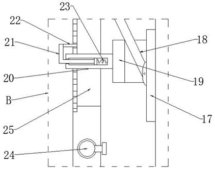
[0036] refer to figure 1 , image 3 and Figure 5 , this embodiment describes the specific structure of the limit protection device mentioned in Embodiment 1 and how to perform limit protection. The limit protection device includes a limit plate 17, a hinged rod 18, a movable ring 19, and a telescopic installation plate 20. Rod 21, positioning plate 22, second return spring 23 and movable groove 25, the inner wall of fixed sleeve 5 is hinged with hinged rods 18 that are symmetrically distributed, and the end of hinged rods 18 is hinged with limit plate 17, fixed sleeve 5 A movable ring 19 is slidably installed inside the movable ring 19, and the movable ring 19 is located between the hinge rod 18 and the fixed sleeve 5, and the circumferential side wall of the movable ring 19 is fixedly connected with a mounting plate 20, and the mounting plate 20 extends to the outside of the fixed sleeve 5 , and the inside of the mounting plate 20 is slidably connected with a telescopic ro...
PUM
 Abstract
Description
Claims
Application Information
 - Generate Ideas
- Intellectual Property
- Life Sciences
- Materials
- Tech Scout
- Unparalleled Data Quality
- Higher Quality Content
- 60% Fewer Hallucinations
Browse by: Latest US Patents, China's latest patents, Technical Efficacy Thesaurus, Application Domain, Technology Topic, Popular Technical Reports.
© 2025 PatSnap. All rights reserved.Legal|Privacy policy|Modern Slavery Act Transparency Statement|Sitemap|About US| Contact US: help@patsnap.com