
Spiral conveying equipment

A screw conveying and equipment technology, which is applied in the field of screw conveying equipment, can solve the problems of poor airtight and pressure-holding performance of equipment, dust and gas leakage, and lower material temperature, so as to achieve reliable sealing structure performance, reduce temperature drop, and reduce reheating energy consumption effect

Pending Publication Date: 2021-03-30
青岛昊辰连铸工程技术有限公司 +1
View PDF0 Cites 0 Cited by
  • Summary
  • Abstract
  • Description
  • Claims
  • Application Information

AI Technical Summary

Problems solved by technology

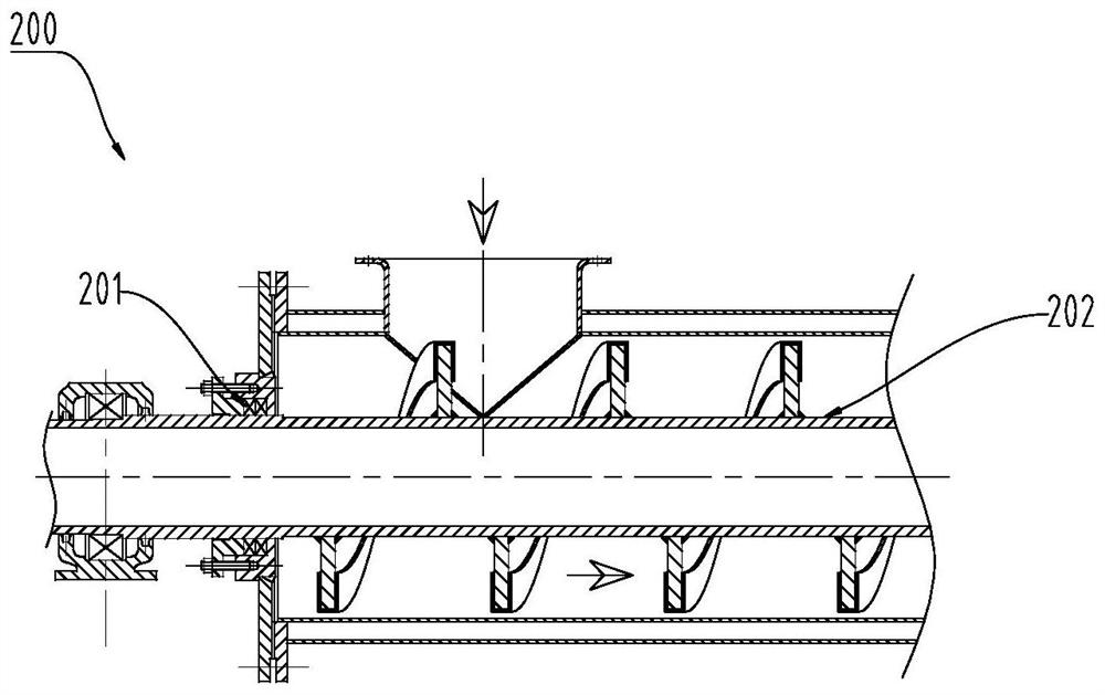
However, under long-term rotational friction, the gap between the filler and the main shaft 202 will become larger and larger, and the performance of the airtight and pressure-holding equipment will become worse and worse, resulting in dust and gas leakage; 2) The temperature drop of the material is large, and the traditional When the screw conveyor 200 conveys high-temperature materials, in order to ensure the performance and life of the equipment, the parts that are in direct contact with the high-temperature materials are usually cooled, that is, water is passed inside the parts to achieve cooling. Such a cooling structure will inevitably directly bring Take a lot of heat from high-temperature materials, resulting in a significant drop in material temperature

Method used


Image

  • Spiral conveying equipment
  • Spiral conveying equipment
  • Spiral conveying equipment

Examples


Embodiment Construction

[0024] In order to better understand the purpose, structure and function of the present invention, a screw conveying device of the present invention will be described in further detail below in conjunction with the accompanying drawings.

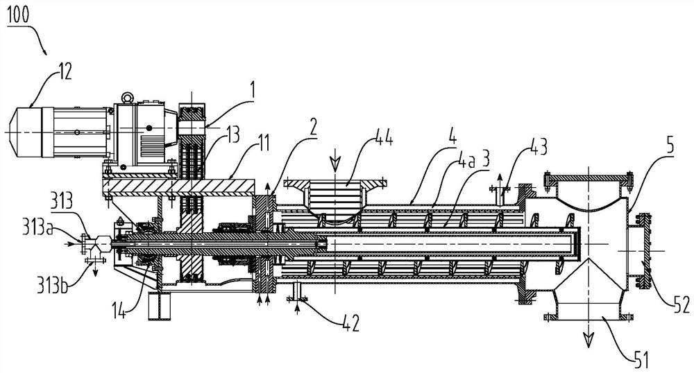
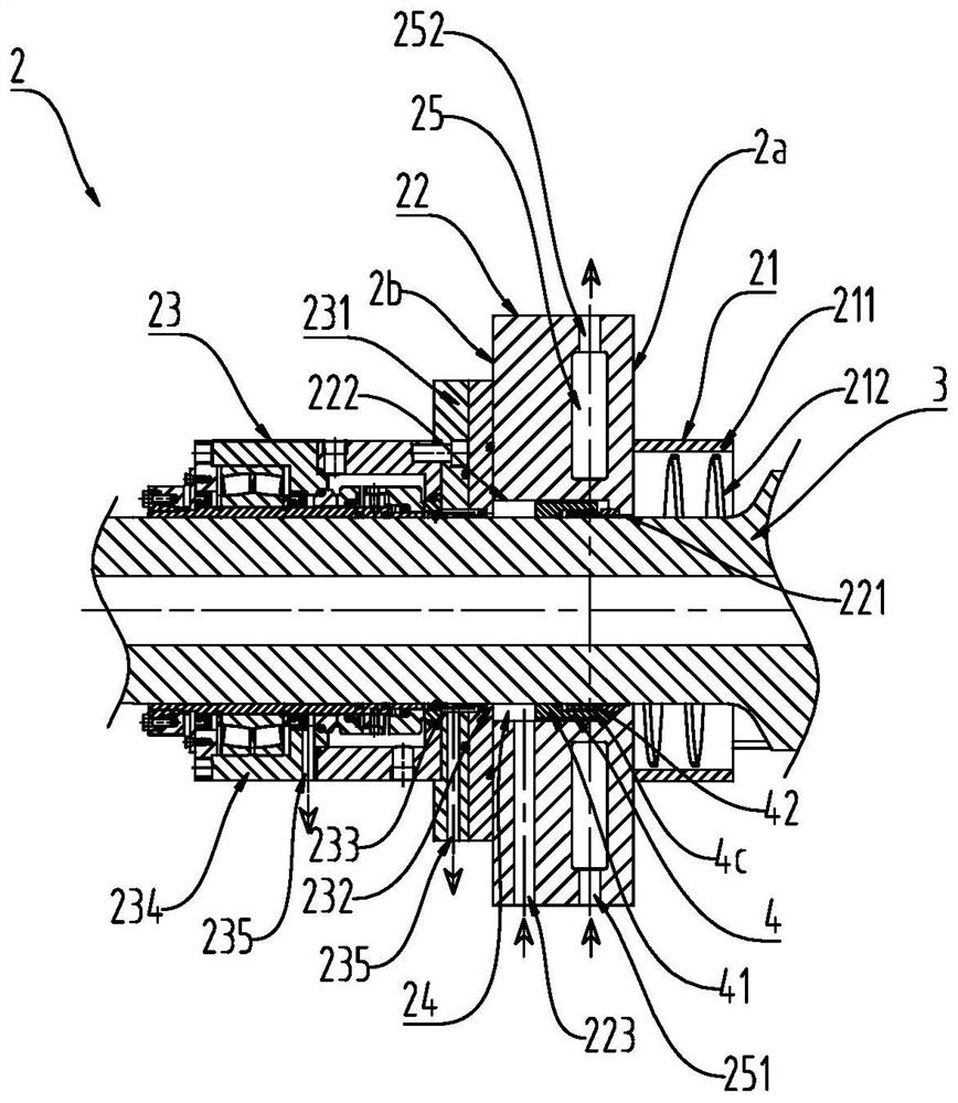
[0025] figure 2 The structure of the screw conveying device 100 according to the embodiment of the present invention is shown. Such as figure 2 As shown, the screw conveying device 100 includes a driving device 1 , a combined sealing device 2 , a screw shaft 3 and a pushing cylinder 4 . Wherein, the screw shaft 3 is coaxially arranged in the pushing cylinder 4 and one end is connected to the driving device 1, and the combined sealing device 2 is sleeved on the screw shaft 3 and is located between the driving device 1 and the pushing cylinder 4, image 3 shows the structure of the combined sealing device 2 according to the embodiment of the present invention, combined with image 3 As shown, the combined sealing device 2 includes a mater...


PUM


Abstract

The invention relates to spiral conveying equipment. The spiral conveying equipment comprises a driving device, a combined sealing device, a spiral shaft and a material pushing barrel, wherein the spiral shaft is coaxially arranged in the material pushing barrel, one end of the spiral shaft is connected with the driving device, the combined sealing device is arranged on the spiral shaft in a sleeving mode and located between the driving device and the material pushing barrel, the combined sealing device comprises a material blocking assembly, a middle flange and a packaging machine sealing assembly which are connected in sequence; the material blocking assembly is located in the material pushing barrel and connected with a material pushing side of the middle flange and used for reversely blocking particles in the material pushing barrel; the middle flange is used for connecting the driving device and the material pushing barrel in a sealed mode, and a gas blocking cavity is formed between the middle flange and the spiral shaft; the packaging machine sealing assembly is connected to the spiral shaft in a sleeving mode and connected with a transmission side of the middle flange and is used for sealing and blocking pressure gas in the gas blocking cavity. According to the spiral conveying equipment, the internal leakproofness can be improved, the service life is prolonged, heat loss of high-temperature materials is reduced, and the purpose of saving energy consumption is achieved.

Description

technical field [0001] The invention belongs to the technical field of screw conveying, and in particular relates to a screw conveying device. Background technique [0002] The screw conveyor is a mechanical device that drives the screw blades by a motor to push the materials in it, so as to achieve the purpose of transportation. It is widely used in various industries, and is often used to convey powdery or granular materials. [0003] figure 1 The structure of a conventional screw conveyor 200 is shown. When the traditional screw conveyor 200 transports materials with a temperature exceeding 500°C, it generally has the disadvantages of poor sealing performance and large temperature drop of materials. Specifically: 1) The sealing performance is poor, and the sealing structure of the traditional screw conveyor 200 is generally a packing type sealing structure 201 . The packing type sealing structure 201 can block dust and withstand a certain pressure. However, under long...

Claims


Application Information

Patent Timeline
Patent Type & Authority Applications(China)
IPC IPC(8): B65G33/14B65G33/26B65G33/24
CPCB65G33/14B65G33/24B65G33/265B65G2201/042
Inventor 吕健徐涛周海川张勇任俊卜二军
Owner 青岛昊辰连铸工程技术有限公司
Learn More