Wet food canning device for pet cat food production
A wet food and cat food technology, applied in the field of canning equipment, can solve the problems of reducing labor workload and large labor workload, and achieve the effect of reducing labor workload and facilitating canning work
- Summary
- Abstract
- Description
- Claims
- Application Information
AI Technical Summary
Problems solved by technology
Method used
Image
Examples
Embodiment 1
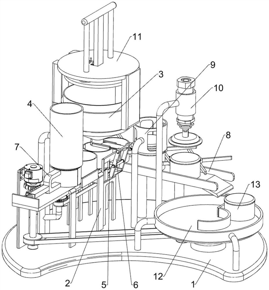
[0034] A wet food canning device for pet cat food production, such as figure 1 , figure 2 , Figure 4 with Image 6 As shown, it includes a bottom plate 1, a pallet frame 2, a wet grain barrel 3, an empty tank barrel 4, a movable seat mechanism 5, and a material stop plate mechanism 6. The top left side of the bottom plate 1 is connected with the pallet frame 2, and the top left side of the bottom Rear side is connected with wet grain barrel 3, bottom plate 1 top left front side is connected with empty tank barrel 4, movable seat mechanism 5 is installed on the bottom plate 1, and material stop plate mechanism 6 is installed between movable seat mechanism 5 and wet grain barrel 3.
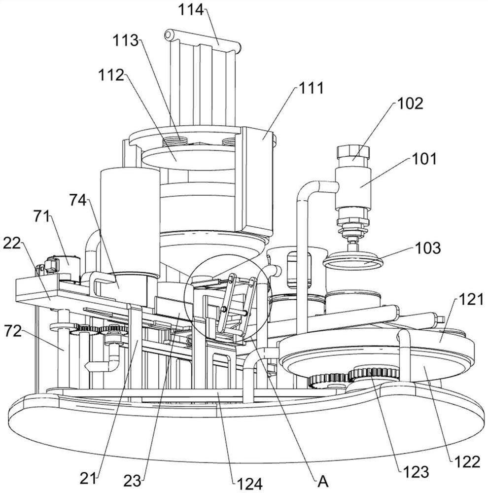
[0035] The pallet frame 2 includes a first support frame 21, a slotted guide plate 22 and a first side baffle plate 23, four first support frames 21 are connected to the left side of the bottom plate 1 top, and one of the tops of the four first support frames 21 A slotted guide plate 22 is conn...
Embodiment 2
[0040] On the basis of Example 1, such as figure 1 , figure 2 with Figure 5 As shown, a can pushing mechanism 7 is also included, and the can pushing mechanism 7 includes a low-speed motor 71, a rotating rod 72, a first sector gear 73, a push rod frame 74, a rack block 75 and a first return spring 76, and the bottom plate 1 top The left front side is equipped with a low-speed motor 71, and the low-speed motor 71 is positioned at the front side of the empty can barrel 4. The output shaft of the low-speed motor 71 is connected with a rotating rod 72 through a shaft coupling, and the bottom end of the rotating rod 72 is connected with the top of the base plate 1 in a rotational manner. The top of the rod 72 is connected with the first sector gear 73, the front side of the slotted guide plate 22 is slidably connected with the push rod frame 74, and the front side of the left side of the push rod frame 74 is connected with the rack block 75, and the rack block 75 is connected wi...
Embodiment 3
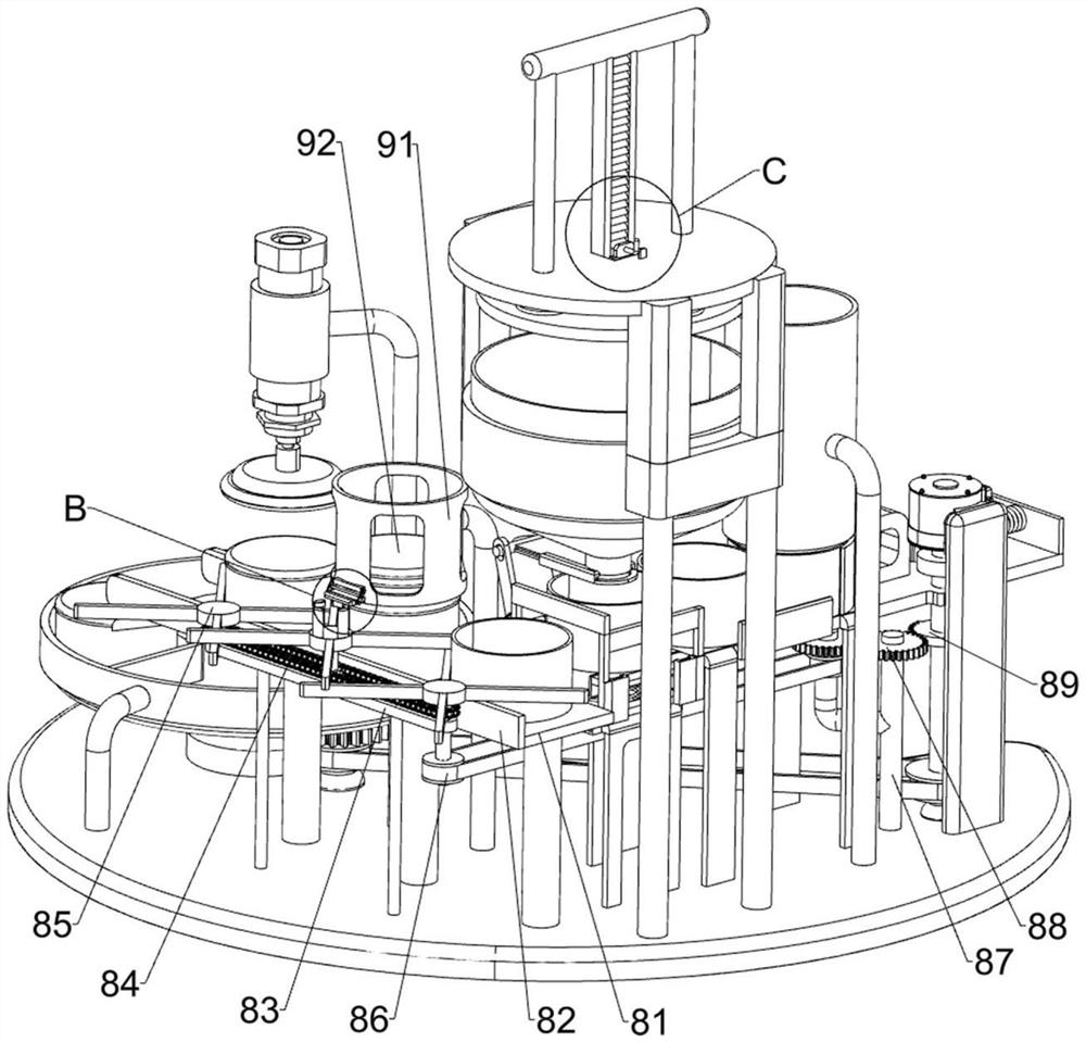
[0043] On the basis of Example 2, such as figure 1 with image 3 As shown, also includes conveying mechanism 8, and conveying mechanism 8 includes material guide plate 81, second side baffle plate 82, mounting frame 83, chain transmission group 84, pull pot wheel 85, first transmission belt group 86, second Support frame 87, first opposite gear set 88 and second sector gear 89, base plate 1 top rear side is connected with material guide plate 81, the front and rear sides of material guide plate 81 are all connected with second side baffle plate 82, base plate 1 Top rear side is connected with installation frame 83, and installation frame 83 is positioned at the rear side of material guide plate 81, is connected with chain drive group 84 in rotation on the installation frame 83, is connected with three pulley wheels 85 on the chain drive group 84, three dials The tank wheels 85 are arranged in a staggered manner. The left front side of the top of the base plate 1 is connected ...
PUM
 Abstract
Description
Claims
Application Information
 - R&D Engineer
- R&D Manager
- IP Professional
- Industry Leading Data Capabilities
- Powerful AI technology
- Patent DNA Extraction
Browse by: Latest US Patents, China's latest patents, Technical Efficacy Thesaurus, Application Domain, Technology Topic, Popular Technical Reports.
© 2024 PatSnap. All rights reserved.Legal|Privacy policy|Modern Slavery Act Transparency Statement|Sitemap|About US| Contact US: help@patsnap.com


